
Motion estimation method and multi-video coding and decoding method and device based on motion estimation

A technology based on visual motion and motion vector, applied in the field of multi-view encoding and decoding methods and devices, can solve the problems of low encoding efficiency, small motion vector code stream transmission, low encoding and decoding efficiency, etc., to ensure accuracy and reduce code stream The effect of improving the transmission volume and encoding efficiency

Inactive Publication Date: 2008-08-13
HUAWEI TECH CO LTD
View PDF0 Cites 17 Cited by
  • Summary
  • Abstract
  • Description
  • Claims
  • Application Information

AI Technical Summary

Problems solved by technology

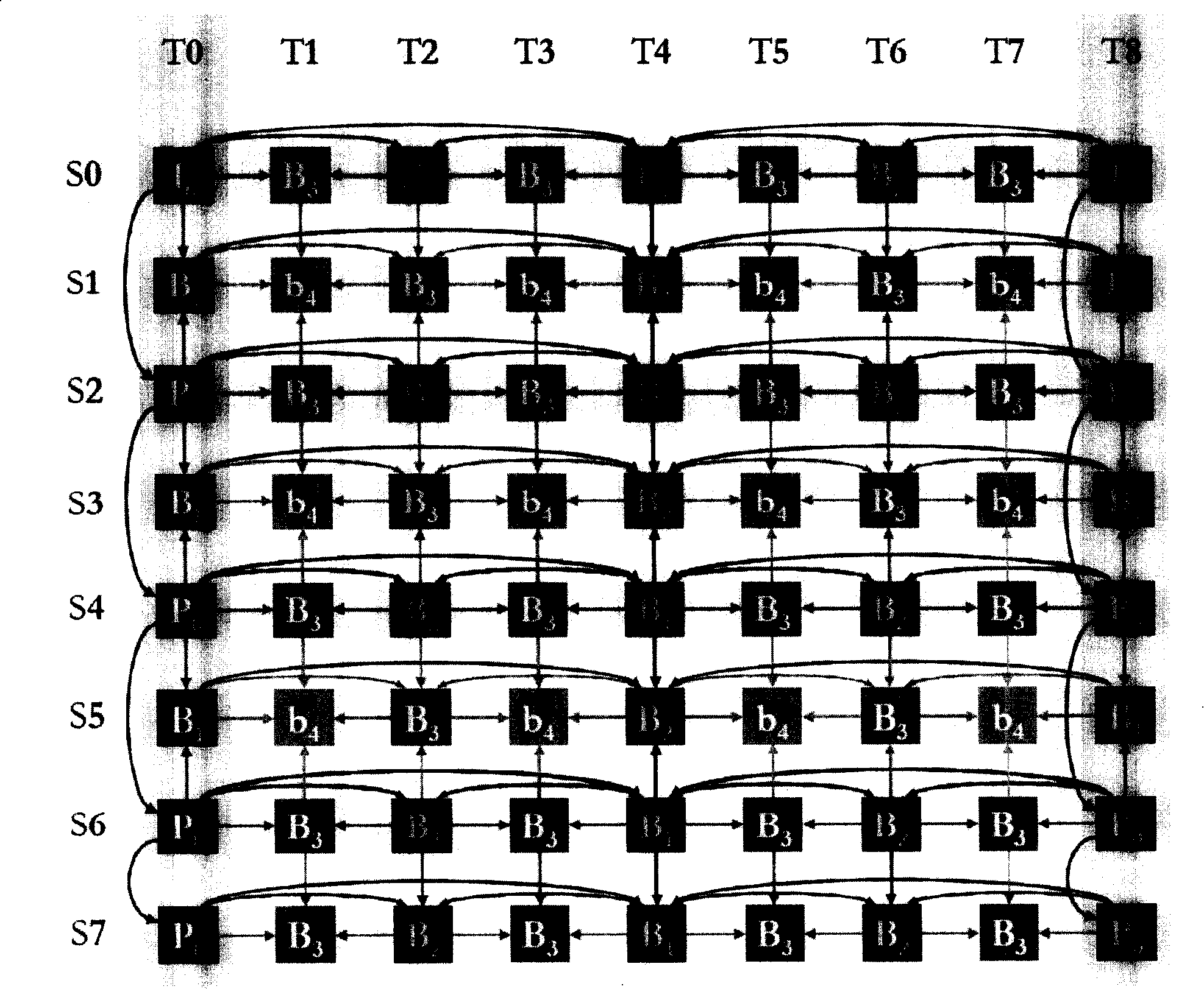
This algorithm has the following disadvantages: On the one hand, when calculating the motion vector, although the temporal correlation and spatial correlation of the multi-view video are taken into account as a whole, for each frame to be encoded, either only the temporal correlation is used , or only the spatial correlation is used, that is, for any frame to be encoded, the temporal and spatial correlation between the views in the multi-view video is not used at the same time, resulting in low encoding efficiency; on the other hand, the algorithm needs to combine all The motion vector of the frame is placed in the coded stream and transmitted to the decoder for decoding, which also leads to low codec efficiency
[0013] It can be seen from the above technical solutions that in the existing multi-view coding, there is no motion estimation method that can better utilize the time-space correlation in multi-view video, so that the bit stream transmission amount of the motion vector obtained by using this motion estimation method is small , and get higher coding efficiency. Correspondingly, the existing multi-view decoding algorithm needs to perform correct decoding based on the motion vectors of all frames

Method used


Image

  • Motion estimation method and multi-video coding and decoding method and device based on motion estimation
  • Motion estimation method and multi-video coding and decoding method and device based on motion estimation
  • Motion estimation method and multi-video coding and decoding method and device based on motion estimation

Examples


Embodiment 1

[0067] This embodiment describes the specific implementation of the motion estimation method of the present invention with reference to the accompanying drawings.

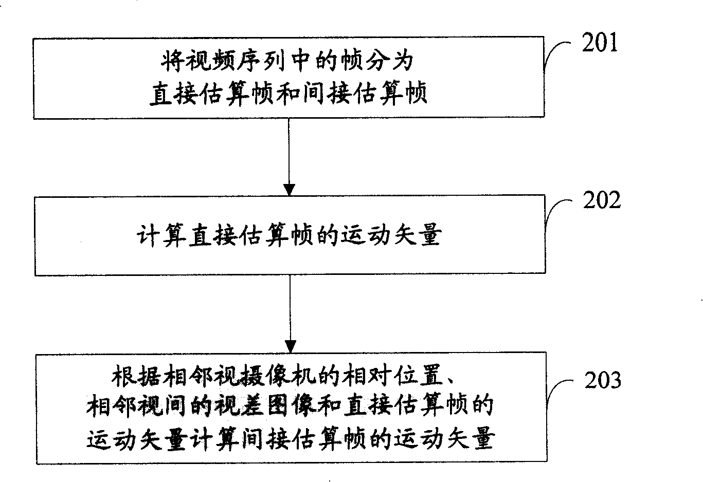
[0068] figure 2 It is a schematic flowchart of a multi-view motion estimation method according to an embodiment of the present invention. see figure 2 , the method includes the following steps:

[0069] Step 201: Divide frames in a video sequence into direct estimation frames and indirect estimation frames.

[0070] In this step, the frames in the video sequence can be divided into direct estimation frames and indirect estimation frames according to the above definitions about direct estimation frames and indirect estimation frames.

[0071] Step 202: Calculate the motion vector of the directly estimated frame.

[0072] In this step, motion estimation can be performed on the directly estimated frame according to the traditional multi-view coding motion estimation algorithm introduced in the background art or ...

Embodiment 2

[0102] This embodiment describes the specific implementation manner of the motion estimation-based multi-view coding method of the present invention with reference to the accompanying drawings.

[0103] Figure 4 It is a schematic flowchart of the multi-view coding method based on motion estimation in Embodiment 2 of the present invention. see Figure 4 , the method includes the following steps:

[0104] Step 401: Divide frames in a video sequence into direct estimation frames and indirect estimation frames.

[0105] Step 402: Calculate the motion vector of the directly estimated frame.

[0106] In this step, motion estimation can be performed on the directly estimated frame according to the traditional multi-view coding motion estimation algorithm introduced in the background art or other motion estimation algorithms in the prior art to obtain its corresponding motion vector.

[0107] Step 403: Calculate the motion vector of the indirectly estimated frame according to the...

Embodiment 3

[0122] This embodiment describes the specific implementation manners of the motion estimation-based multi-view decoding method and device of the present invention with reference to the accompanying drawings.

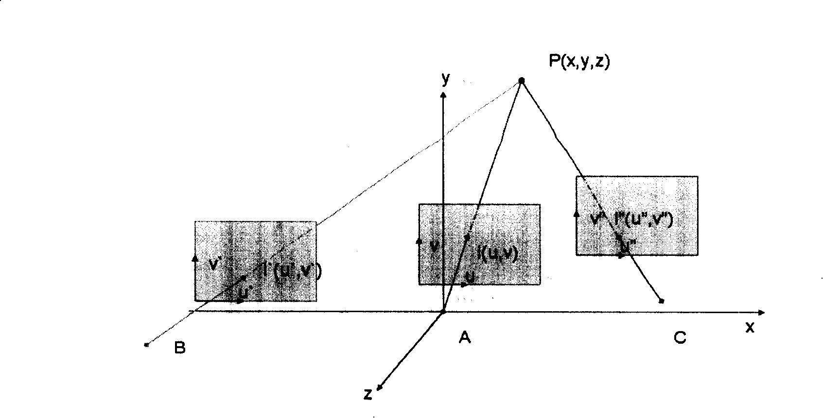
[0123] In this embodiment, same as the first embodiment, S1 is regarded as corresponding to image 3 In the video sequence captured by camera A shown, S0 corresponds to image 3 The video sequence captured by camera B shown in S2 corresponds to image 3 The video sequence captured by camera C is shown, therefore, image 3 The relative positional relationship between the cameras and the coordinates of the cameras are also applicable to this embodiment.

[0124] Figure 6 It is a schematic flowchart of the multi-view decoding method based on motion estimation in Embodiment 3 of the present invention. see Figure 6 , the method includes the following steps:

[0125]Step 601: Divide frames in a video sequence into direct estimation frames and indirect estimation frames...


PUM


Abstract

The embodiments of the present invention provide a estimation method of multi-look motion. The method includes following steps: dividing the frame in the video sequence into an explicitly estimating frame and an indirectly estimating frame; calculating motion vector of the explicitly estimating frame; computing motion vector of the indirectly estimating frame according to the relative position of adjacent look vidicons, the anaglyph of adjacent looks and the motion vecto of the explicitly estimating frame. The embodiment of the invention also provides another motion estimating method, and method and device of multi-llo code based on the motion estimating method, multi-look decoding method and device. Using the invention substantially utilizes time relativity and space relativity between adjacent looks in the multi-look video under this condition that the invention ensures precision of motion estimation, reducing bit rate transport layer and improving efficiency of multi-llo code.

Description

technical field [0001] The present invention relates to video image coding and decoding technology, in particular to a motion estimation method, a multi-view coding and decoding method and device based on motion estimation. Background technique [0002] Current video coding standards such as the H.261, H.263, H.263+, and H.264 standards formulated by the International Telecommunication Union (ITU, International Telecommunication Union), and the standards established by the Moving Picture Experts Group (MPEG, Moving Picture Experts Group) MPEG-1, MPEG-2, MPEG-3, MPEG-4, etc. are all based on the hybrid coding (Hybrid Coding) framework. The so-called hybrid coding framework is a video image coding method that mixes time and space. When coding, first perform intra-frame and inter-frame prediction to obtain the original image prediction image to eliminate the correlation in the time domain; then predict the image according to the original image and The difference between the ac...

Claims


Application Information

Patent Timeline
IPC IPC(8): H04N7/26H04N7/32H04N7/50H04N19/513H04N19/597
Inventor 史舒娟陈海
Owner HUAWEI TECH CO LTD
Learn More