Device for regulating chair angle

一种角度调节装置、座椅的技术,应用在机械领域,能够解决滑块的棘齿与棘轮棘齿啮合强度低等问题,达到结构紧凑、双边解锁性能好、强通用性的效果

Active Publication Date: 2008-08-20
HUBEI AVIATION PRECISION MASCH TECH CO LTD
View PDF1 Cites 19 Cited by
  • Summary
  • Abstract
  • Description
  • Claims
  • Application Information

AI Technical Summary

Problems solved by technology

[0005] In view of this, the present invention is to provide a seat angle adjustment device to solve the problem in the prior art that in the single-point support mode, the ratchet of the slider and the ratchet of the ratchet will be meshed after the seat back is stressed. low intensity problem

Method used


Image

  • Device for regulating chair angle
  • Device for regulating chair angle
  • Device for regulating chair angle

Examples


Embodiment Construction

[0027] The following describes in detail the embodiments of the present invention with reference to the accompanying drawings.

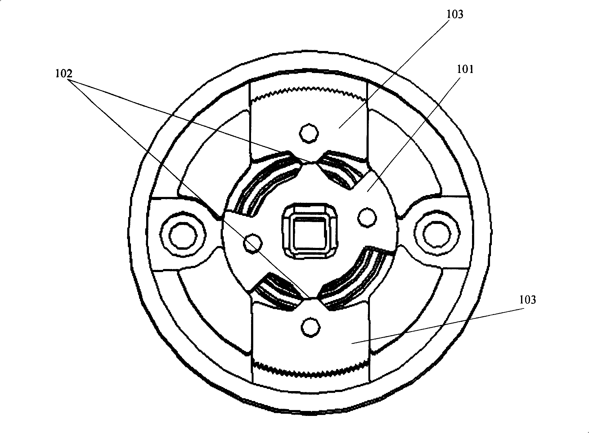
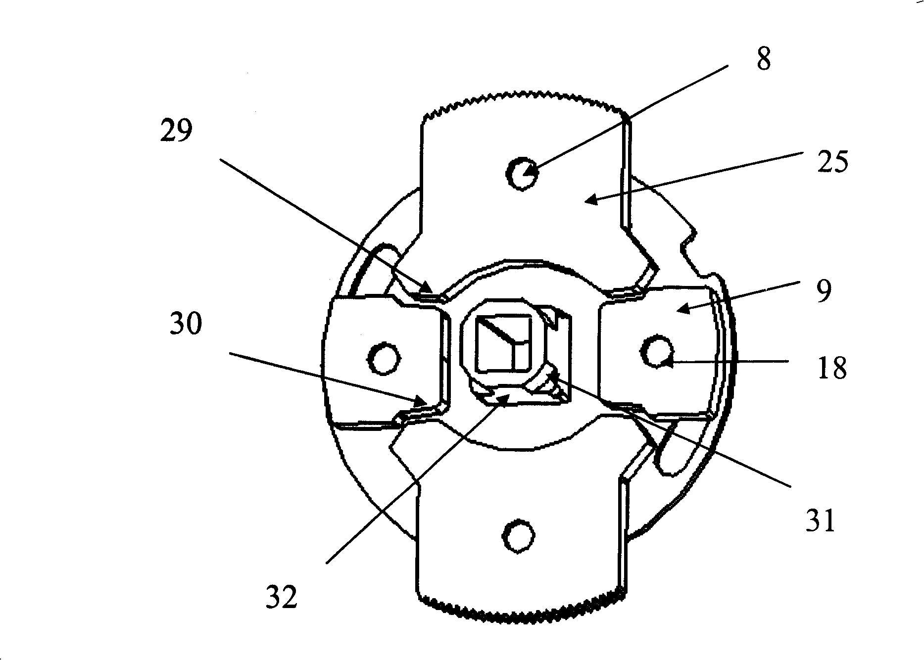
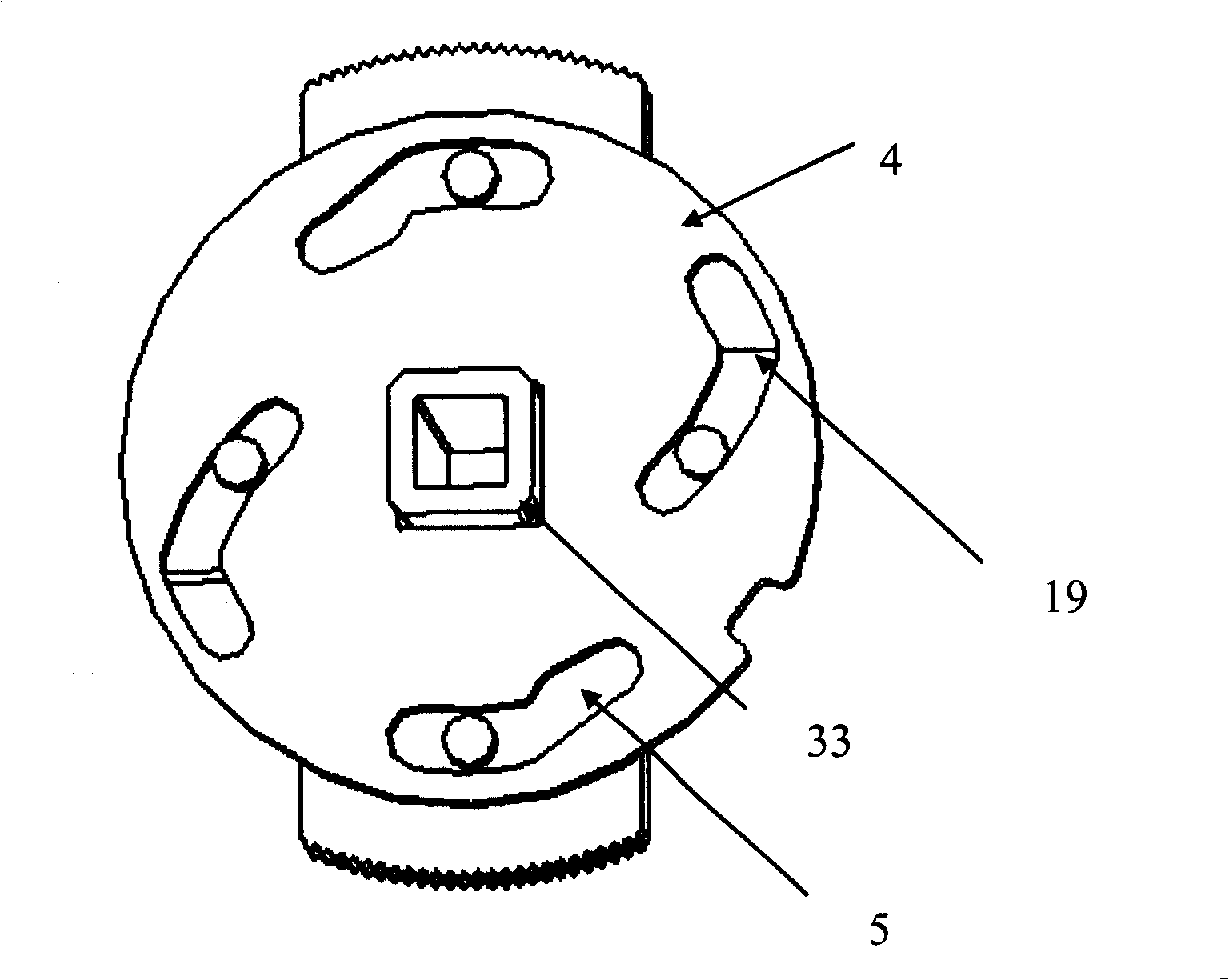
[0028] see figure 2 , image 3 , Figure 4 , in this embodiment, first describe the locking part of the cam 4, in order to better understand the technical core of the present invention on locking. In the cam 4, there are two symmetrical chute 19 and two symmetrical chute 5, two sliding blocks 25 its own boss 8 is connected with the chute 5, and two wedge blocks 9 pass through their own boss 18 Connect with the chute 19. After the locking part of the cam 4 is used for the angle adjustment of the seat, a brand-new seat angle adjustment device is formed.

[0029] After the cam 4 rotates, the two symmetrical self-locking surfaces 29 on the slider 25 and the two symmetrical self-locking surfaces 30 on the wedge block 9 form a two-point lock.

[0030] The seat angle adjusting device with the locking part of the cam 4 will be described in detail below...


PUM


Abstract

The invention discloses a seat angle adjusting device, belonging to mechanical technical field, which comprises a cam, a reset spring, a slideway plate, a ratchet wheel and a central shaft. The ratchet wheel is connected with the central shaft and the outer hook of the reset spring is fixed in the hole of the slideway plate. A sliding block is arranged in the slideway of the slideway plate and the lug boss of the sliding block is connected with the slideway of the cam. A wedge-shaped block is arranged in the slideway of the slideway plate and the lug boss of the wedge-shaped block is connected with the slideway of the cam. The two slideways are in vertical direction. The self locking surfaces of the sliding block and the wedge-shaped block form two-point locking after fixing the cam position by the central shaft under the reset spring. The seat angle adjusting device has the advantages of compact structure, compact size, high strength, good property of two-side unlocking and high adjusting precision, and can adjust the backrest angle and fold the backrest rapid.

Description

technical field [0001] The invention relates to the field of mechanical technology, in particular to a seat angle adjusting device. Background technique [0002] At present, many seats can realize the functions of angle adjustment and fast folding of the seat back, and realize the locking function after the angle adjustment, so that the angle between the seat and the seat back is fixed. [0003] The implementation method in the prior art is: see Chinese Patent No. ZL 200420017699.4 utility model name is leaf spring type seat angle adjustment and seat back folder core device. Such as figure 1 As shown, in this device, the locking cam 101 supports the two sliders 103 through its own two self-locking surfaces 102 under the external force of the return spring, so that the slider ratchets on the two sliders 103 and the ratchet ratchet The meshing between the teeth is more firm, so that the angle of the seat and the seat back of the seat can be adjusted to fix the angle of the s...

Claims


Application Information

Patent Timeline
Patent Type & Authority Applications(China)
IPC IPC(8): A47C1/024A47C1/026
CPCB60N2/236
Inventor 罗贤虎黄正坤
Owner HUBEI AVIATION PRECISION MASCH TECH CO LTD
Why Eureka
Try Eureka