Application system for potential, kinetic and air energy of vehicle
A technology for application systems and vehicles, applied in the field of application systems, can solve problems such as waste
Inactive Publication Date: 2008-08-20
孙振国
View PDF0 Cites 3 Cited by
- Summary
- Abstract
- Description
- Claims
- Application Information
AI Technical Summary
Problems solved by technology
However, a kind of energy naturally formed by vehicles in operation has not been paid attention to by people for a long time and wasted in vain.
Method used
View moreImage
Smart ImageViewing Examples

Examples
Embodiment Construction
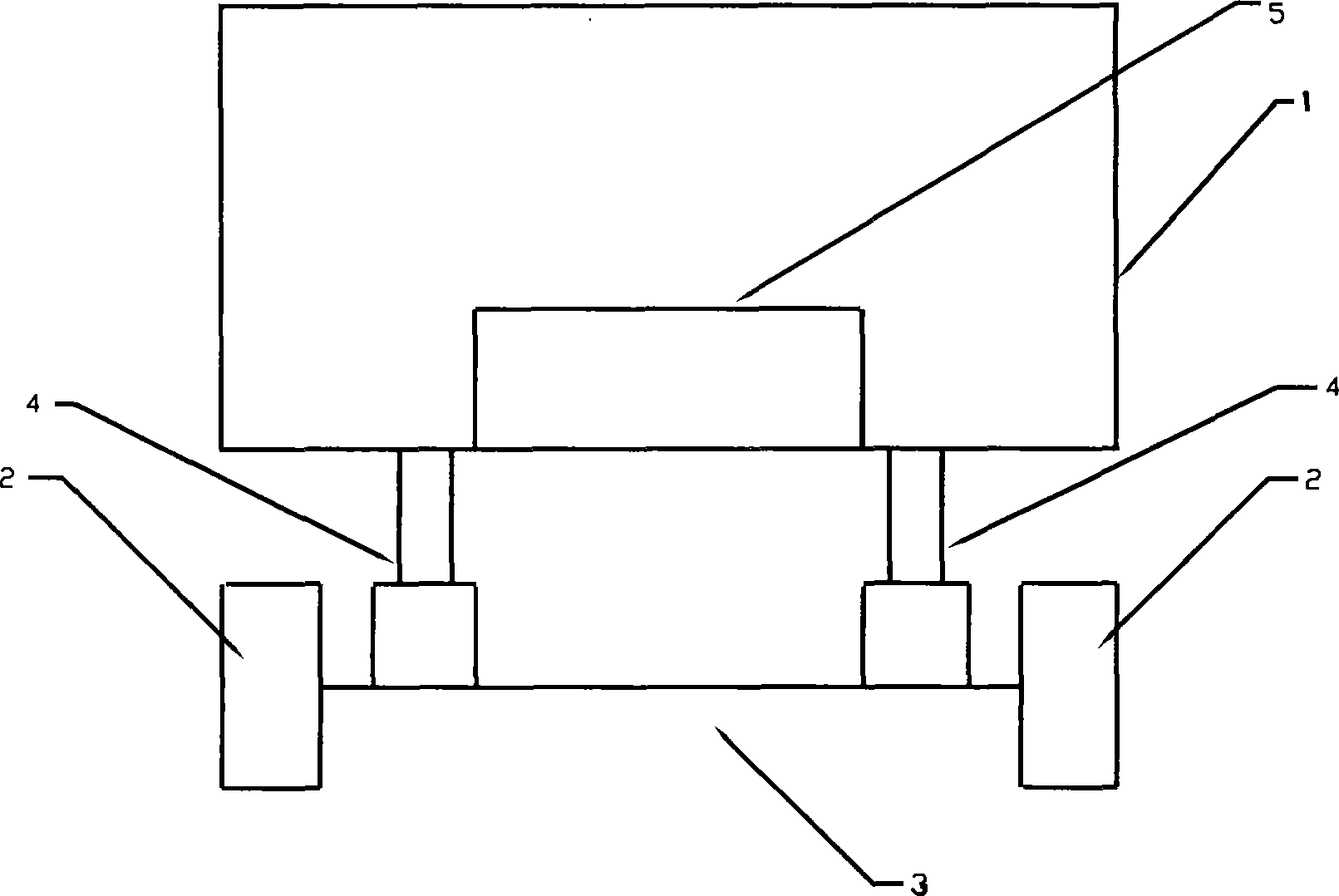
[0011] As shown in Figure 1: piston type air pump (air compressor) 4 is installed between vehicle body 1 and axle 3, and its two ends are connected with vehicle body 1 and axle 3 respectively (or its one end is connected with vehicle body 1 or axle 3), and axle 3 is connected with wheel 2; Air pump (air compressor) 4 is connected with air storage tank 5 by high-pressure air pipe, and air storage tank 5 is connected with other gas-using devices with high-pressure air pipe again.
Login to View More PUM
 Abstract
The invention discloses a vehicle potential and pneumatic application system, belonging to the technical field of the development and application of new energy, which comprises the vehicle potential and pneumatic application method and the device. The vehicle potential and pneumatic application system is characterized in that: the potential energy produced in the bumping of the vehicle is used to drive a piston air pump (air compressor) and thus producing the high pressure pneumatic energy which can be conveniently used. The piston air pump (air compressor) is arranged between the vehicle body and the wheel shaft. Both ends (one end) of the pump (air compressor) are (is) connected with the vehicle body and the wheel shaft. The pump (air compressor) is connected by the high pressure windpipe and the air storage tank, which is connected by the high pressure windpipe and other air sets. The vehicle potential and pneumatic application system has the advantages of effectively reducing the energy consumption of the vehicle operation, easing the pressure of the vehicle damping system, prolonging the service life of the vehicle damping system and enhancing the damping effect of the vehicle.
Description
Technical field [0001] The invention relates to the development and utilization of a new type of energy, in particular to an application system capable of converting the potential energy of a vehicle when it bumps into gas energy. Background technique [0002] For a long time, vehicles have been widely used in people's production and life. Today, it can be said that people cannot do without vehicles in their production and life. However, in recent years, the continuous rise of various energy prices has continuously increased the operating costs of various vehicles. Vehicle manufacturers all over the world are working hard to develop various new energy-saving vehicles to adapt to people's demand for vehicles under the situation of energy shortage. usage requirements. However, a kind of energy naturally formed in the operation of vehicles has not been paid attention to by people for a long time and wasted in vain. Contents of the invention [0003] In order to maximize the...
Claims
Login to View More Application Information
Patent Timeline
 IPC IPC(8): B60K25/10
Inventor 孙振国
Owner 孙振国