Pavement planeness automatic detection device and detecting method

An automatic detection device and automatic detection technology, applied in measurement devices, optical devices, instruments, etc., can solve the problems of low measurement efficiency, many error sources, poor repeatability, etc., and achieve high detection efficiency, fewer error sources, and measurement errors. small effect

Active Publication Date: 2008-08-20
南通滨睿智能科技有限公司
View PDF0 Cites 66 Cited by
  • Summary
  • Abstract
  • Description
  • Claims
  • Application Information

AI Technical Summary

Benefits of technology

This technology helps reduce measuring errors caused by factors like road conditions or other vehicles' movements during driving without compromising its ability to accurately detect obstacles such as car-bumping attacks. It uses sensors that measure changes over time instead of just comparing measurements from different points along their length, resulting in more accurate data compared with traditional techniques. Additionally it eliminates any interference signals between nearby objects due to the movement being driven through them. Overall, this technology improves safety measures for drivers while reducing damage risk associated therewith.

Problems solved by technology

This patented technical problem addressed in this patents relates to improving the performance and reliance of automated road surface assessment systems due to their high errors caused by factors like noise or irregularities in measurements made over long distances along roads. Current solutions involve expensive and time-consuming manual inspections, while current electronic devices lack precise analysis capabilities without sacrifices resolution speed and stability.

Method used


Image

  • Pavement planeness automatic detection device and detecting method
  • Pavement planeness automatic detection device and detecting method
  • Pavement planeness automatic detection device and detecting method

Examples


specific Embodiment approach 1

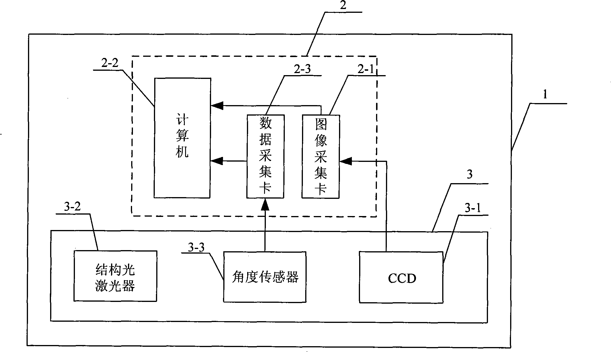
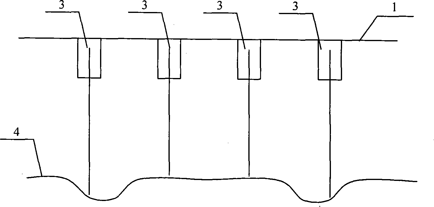
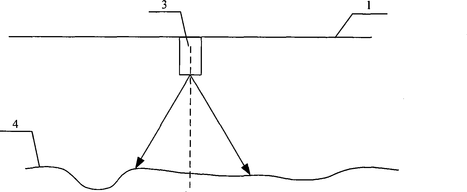
[0018] Specific implementation mode one: combine figure 1 ~ Fig. 5 illustrates this embodiment. This embodiment is composed of a processing system 2 and a three-dimensional structured light visual detection component 3. The three-dimensional structured light visual detection component 3 is arranged laterally on the cross section of the bottom of the car body 1. The three-dimensional structured light visual detection component 3 includes a structured light laser 3-2 and an area array CCD 3-1, characterized in that the structured light strip emitted by the structured light laser 3-2 covers the longitudinal road surface, and the camera of the area array CCD 3-1 faces the road below the structured light laser 3-2 4, to shoot structured light laser 3-2 projected onto the road surface 4 light strip images covering the longitudinal road surface; the three-dimensional structured light visual detection component 3 also includes an angle sensor 3-3; the output terminals of the three-dime...

specific Embodiment approach 2

[0019] Specific implementation mode two: combination figure 1 Illustrate the present embodiment, present embodiment and specific embodiment one difference is that processing system 2 is made up of image acquisition card 2-1, data acquisition card 2-3 and computer 2-2; The output terminal connection image of area array CCD3-1 The input end of the acquisition card 2-1, the image acquisition card 2-1 is connected to the inside of the computer 2-2, the output end of the angle sensor 3-3 is connected to the input end of the data acquisition card 2-3, and the output of the data acquisition card 2-3 The terminal is connected to the inside of the computer 2-2. Other compositions and connection methods are the same as those in Embodiment 1. Image acquisition card 2-1 adopts OK_M20A from Beijing Jiaheng Zhongzi, data acquisition card 2-3 adopts Taiwan Advantech PCI-1710L, computer 2-3 adopts Taiwan Advantech industrial computer.

specific Embodiment approach 3

[0020] Specific embodiment three: this embodiment is described in conjunction with Fig. 4, the difference between this embodiment and specific embodiment one is that the angle sensor 3-3 is arranged at the position between the structured light laser 3-2 and the area array CCD3-1; other components The connection method is the same as that in the first embodiment.


PUM


Abstract

The invention discloses a device and a method for automatically detecting the flatness of road surfaces, relates to the field of road surface flatness detection, and aims at overcoming the defects of inaccurate information, a plurality of error sources, complex structure and unsolvable influence of vehicle body obliquity in the prior art. A three-dimensional optical vision detecting component of the device for automatically detecting the flatness of road surfaces comprises an angle sensor and an output end that is connected with an input end of a processing system; structured light bars that are emitted by a laser device of structured lights cover the longitudinal road surface, and the processing system is arranged inside the vehicle body. The method for automatically detecting the flatness of road surfaces comprises the followings steps: (1) the structured light bars of the laser device of structured lights implement imaging on a CCD area array after being modulated by three-dimensional road surface information, and simultaneously shaking information of the vehicle body is collected, and three-dimensional information is computed; (2) disease influence is eliminated by filtering; (3) depth displacement of the road surfaces is computed in the interval of 250mm, and an IRI result of a corresponding road section is computed; (4) data storage, analysis and display are implemented. The device and the method for automatically detecting the flatness of road surfaces have the advantages of complete and accurate extracted longitudinal outline, simple structure, and the eliminated influence of vehicle shaking.

Description


Claims


Application Information

Patent Timeline
Owner 南通滨睿智能科技有限公司
Why Eureka
Try Eureka