Pavement planeness automatic detection method

An automatic detection and flatness technology, applied in the direction of measuring devices, instruments, optical devices, etc., can solve the problems of low measurement efficiency, signal aliasing, and many error sources, and achieve high detection efficiency, eliminate signal aliasing, and error source less effect

Active Publication Date: 2009-12-23
南通滨睿智能科技有限公司
View PDF5 Cites 0 Cited by
  • Summary
  • Abstract
  • Description
  • Claims
  • Application Information

AI Technical Summary

Problems solved by technology

[0008] The present invention aims to solve the problems of low precision and poor repeatability caused by the defects of many error sources, low measurement efficiency, signal aliasing and inability to solve the influence of car body tilt in existing flatness testing instruments, and proposes a road surface Flatness automatic detection method

Method used


Image

  • Pavement planeness automatic detection method
  • Pavement planeness automatic detection method
  • Pavement planeness automatic detection method

Examples


specific Embodiment approach 1

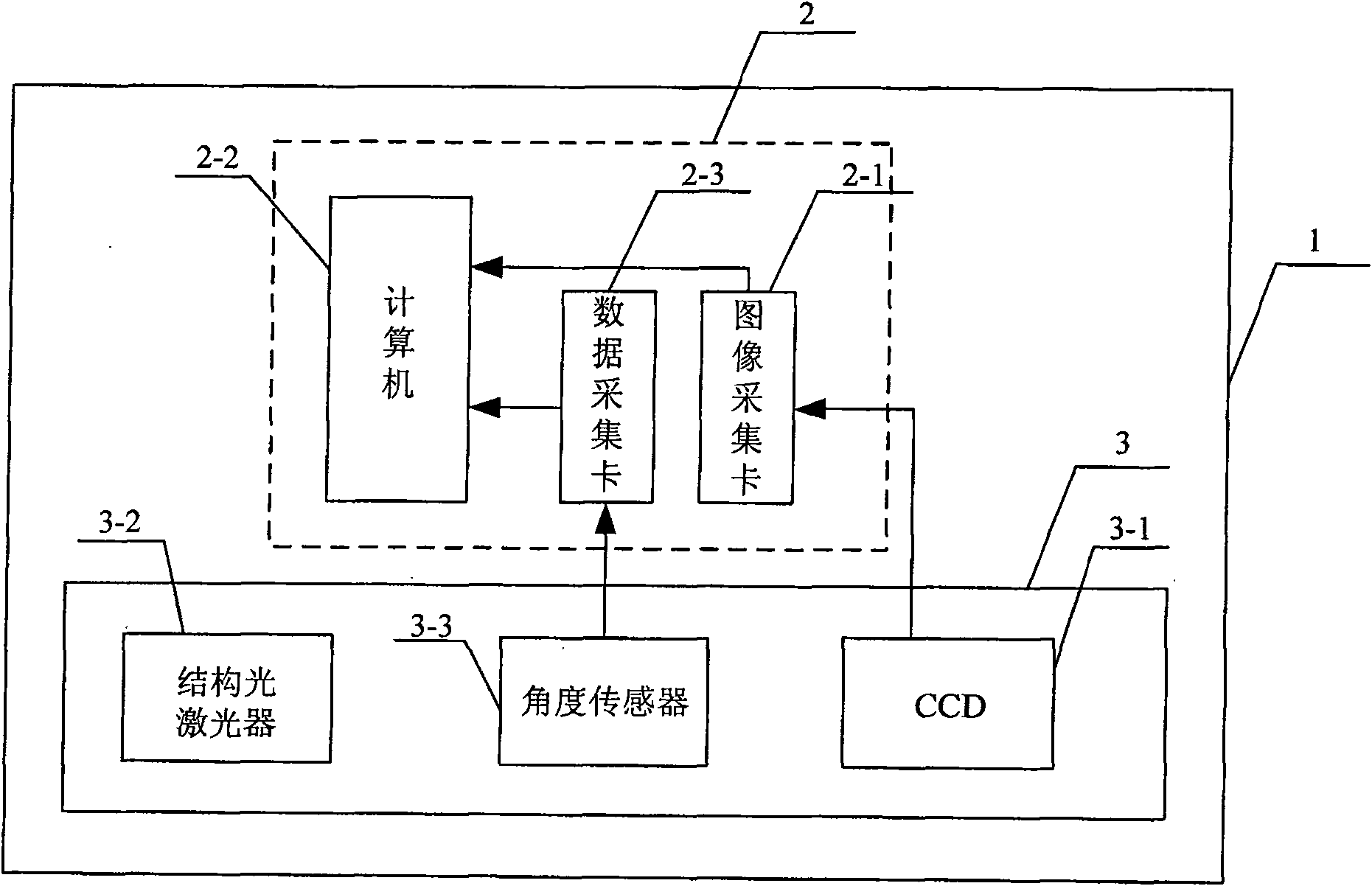
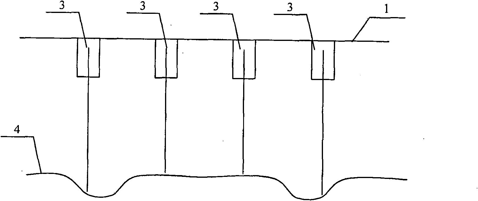
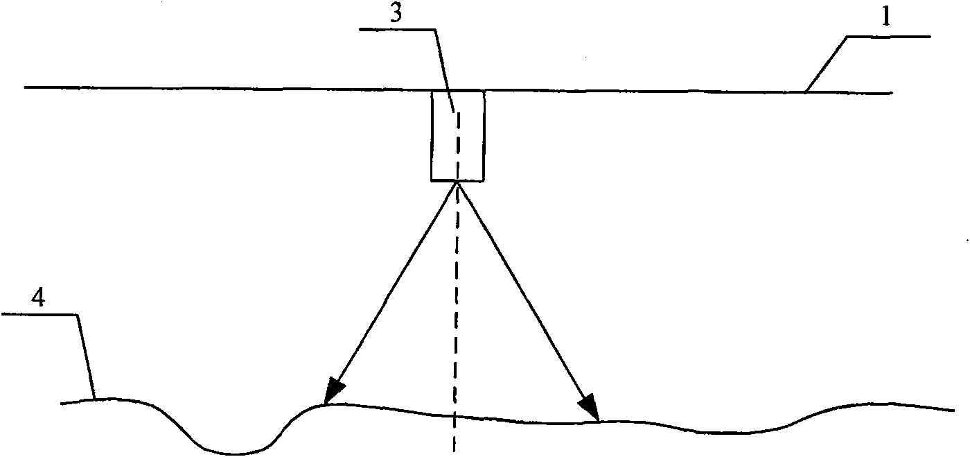
[0021] Specific implementation mode one: combine Figure 1 to Figure 5 Describe this embodiment. This embodiment is composed of a processing system 2 and a three-dimensional structured light vision detection component 3. The three-dimensional structured light vision detection component 3 is arranged laterally on the cross section of the bottom of the car body 1. The three-dimensional structured light vision detection component 3 includes a structure The optical laser 3-2 and the area array CCD3-1 are characterized in that the structured light strips emitted by the structured light laser 3-2 cover the longitudinal road surface, and the camera of the area array CCD3-1 faces the road surface 4 below the structured light laser 3-2, so as to Shoot the light strip image projected by the structured light laser 3-2 onto the road surface 4 and cover the longitudinal road surface; the three-dimensional structured light visual detection component 3 also includes an angle sensor 3-3; the o...

specific Embodiment approach 2

[0022] Specific implementation mode two: combination figure 1 Illustrate the present embodiment, present embodiment and specific embodiment one difference is that processing system 2 is made up of image acquisition card 2-1, data acquisition card 2-3 and computer 2-2; The output terminal connection image of area array CCD3-1 The input end of the acquisition card 2-1, the image acquisition card 2-1 is connected to the inside of the computer 2-2, the output end of the angle sensor 3-3 is connected to the input end of the data acquisition card 2-3, and the output of the data acquisition card 2-3 The terminal is connected to the inside of the computer 2-2. Other compositions and connection methods are the same as those in Embodiment 1. Image acquisition card 2-1 adopts OK_M20A from Beijing Jiaheng Zhongzi, data acquisition card 2-3 adopts Taiwan Advantech PCI-1710L, computer 2-3 adopts Taiwan Advantech industrial computer.

specific Embodiment approach 3

[0023] Specific implementation mode three: combination Figure 4 Describe this embodiment, the difference between this embodiment and the specific embodiment is that the angle sensor 3-3 is arranged at the position between the structured light laser 3-2 and the area array CCD3-1; other composition and connection methods are the same as the specific embodiment one same.


PUM


Abstract

The automatic detection method of road surface roughness, which involves the field of road surface smoothness detection, aims at the disadvantages of inaccurate information, many error sources, complex structure, and inability to solve the influence of vehicle body tilt. Its three-dimensional structured light visual detection component also includes Angle sensor; the output end of the three-dimensional structured light vision detection component is connected to the input end of the processing system; the structured light strip emitted by the structured light laser covers the longitudinal road surface, and the processing system is located in the vehicle body. The method is as follows: 1. After the structured light strip of the structured light laser is modulated by the three-dimensional information of the road surface, it is imaged on the area array CCD, and the bumping information of the vehicle body is collected at the same time, and the three-dimensional information is obtained through calculation; second, the influence of the disease is removed by filtering; third, Calculate the road elevation difference at intervals of 250mm, and calculate the IRI results of the corresponding road sections; 4. Data storage, analysis and display. The advantage is that the extracted longitudinal profile is complete and accurate, the structure is simple, and the influence of vehicle bumps is eliminated.

Description

technical field [0001] The invention relates to the field of road surface smoothness detection, in particular to an automatic detection method for the flatness of road surfaces, especially high-grade road surfaces. Background technique [0002] With the rapid development of my country's transportation industry, the mileage of highway traffic is increasing sharply. Pavement roughness is one of the most important indicators for evaluating road quality. It has a direct impact on vehicle safety, comfort and operating costs, and occupies a very important position in road maintenance. Therefore, how to efficiently and accurately detect and evaluate road roughness indicators has always been a matter of great concern to highway departments. In the process of highway development, various testing instruments and technologies have been developed, and corresponding testing procedures have been formulated. [0003] At present, the existing automatic detection equipment for road surface...

Claims


Application Information

Patent Timeline
Patent Type & Authority Patents(China)
IPC IPC(8): G01B11/30
Inventor 刘宛予谢凯黄建平
Owner 南通滨睿智能科技有限公司
Why Eureka
Try Eureka