Method and device for determining a leak resistance for at least one wire of a subscriber connection line comprising several wires in a communications network

A leakage resistance and connecting line technology, which is used in high resistance measurement, telephone communication, line transmission parts, etc., can solve the problems of value distortion and value distortion of leakage current measurement

Inactive Publication Date: 2012-01-11
ノキアソリューションズアンドネットワークスゲゼルシャフトミットベシュレンクテルハフツングウントコンパニーコマンディトゲゼルシャフト
View PDF0 Cites 0 Cited by
  • Summary
  • Abstract
  • Description
  • Claims
  • Application Information

AI Technical Summary

Problems solved by technology

[0009] The leakage resistance R assigned to the prior art is used to determine the a and R b And in the method of line occupation ("RC measurement"), the following question now arises: The ringing capacitance C makes the measured value of the leakage current on the wires (a and b) of the user connection line TAL in the case of the current method distortion
[0018] Here, as mentioned above, a disadvantage of the above method for RC measurement is the fact that the ringing capacitance arranged between the two conductors a and b makes I Ra1 and I Ra2 The value is distorted

Method used


Image

  • Method and device for determining a leak resistance for at least one wire of a subscriber connection line comprising several wires in a communications network
  • Method and device for determining a leak resistance for at least one wire of a subscriber connection line comprising several wires in a communications network
  • Method and device for determining a leak resistance for at least one wire of a subscriber connection line comprising several wires in a communications network

Examples


Embodiment Construction

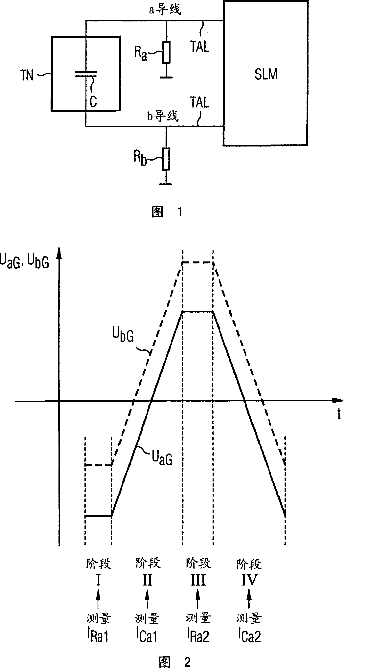
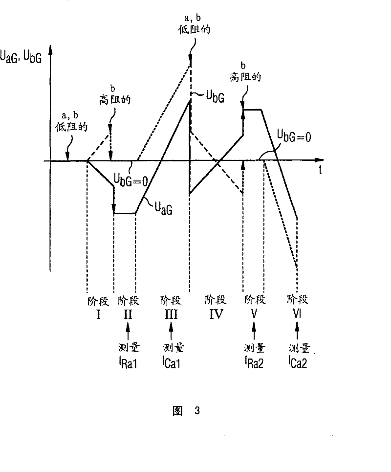
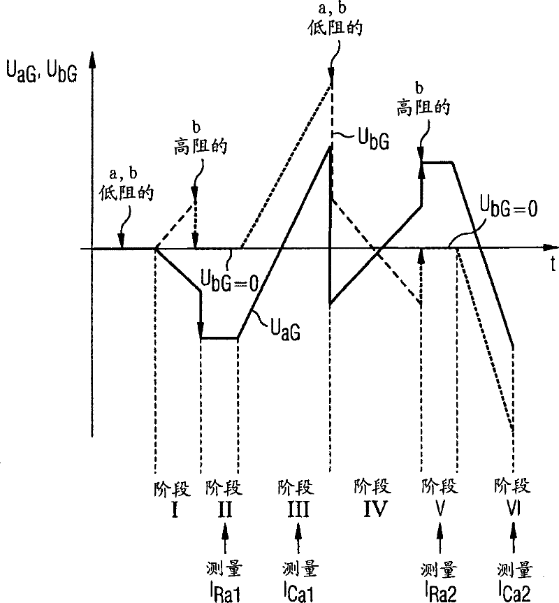
[0030] exist image 3 A time sequence according to the invention for determining the resistance between a conductor of a subscriber line and ground is shown in . The method is described here by way of example with the aid of a combined determination of the leakage resistance and line occupancy ("RC measurement") of the a-conductor of a subscriber line comprising two conductors (a and b).

[0031] In the method according to the invention, initially the a-conductor and the b-conductor of the subscriber line are switched to low resistance. In the first step (Phase I), the constant falling voltage U aG (indicated by a solid line in the figure) is applied to the conductor a to be measured, whereby the voltage U on the second conductor b is conditional on simultaneous coupling of two conductors a and b bG (indicated by a dotted line) has a correspondingly constant rising characteristic curve. Two voltages U aG or U bG In this case, a predeterminable end value is reached in each...


PUM


Abstract

While determining a leak resistance (Ra, Rb) of a subscriber connection line (TAL) provided, for example, with two wires (a, b) in a communications network, a capacitor (C) connected between said two wires is discharged prior to measuring leakage currents (IRa1, IRa2). For this purpose, prior to be connected to a high resistance of the other wire (b), the measurable wire (a) and the other mentioned wire (b) are supplied with a constantly falling and increasing voltage (UaG, UbG). For that, the final value of said tensions (UaG, UbG) is determined in such a way that, when the connection to the high resistance of the other wire (b) is produced, the voltage of said wire (b) is equal to 0 volt. The leakage current is measured only when the discharge process is over, thereby making it possible to avoid an incorrect measurement caused by a current coming from the capacitor (C).

Description

technical field [0001] The invention relates to a method and a device for determining the leakage resistance of at least one conductor of a subscriber line having a plurality of conductors in a communication network. Background technique [0002] Operators of communication networks, such as conventional telephone networks and telephone networks, in addition to providing efficient data transmission (in telephone networks: voice), usually provide users or customers with a large number of other capabilities and user performance features. For example, conference calls, transmission and suppression of call numbers, call forwarding or metering pulses are among the functions mentioned. [0003] The operator of the telephone network must also measure the electrical properties of the subscriber connection lines (TAL) at the time of customer complaints or during routine tests or inspections of these services. However, no audible sound from the connected end device is allowed during s...

Claims


Application Information

Patent Timeline
Patent Type & Authority Patents(China)
IPC IPC(8): H04M3/30G01R31/28
CPCH04M3/305H04B3/46G01R27/025G01R31/28H04M3/30
Inventor R·多林格
Owner ノキアソリューションズアンドネットワークスゲゼルシャフトミットベシュレンクテルハフツングウントコンパニーコマンディトゲゼルシャフト
Why Eureka
Try Eureka