
Millimeter wave integration multichannel active transmitting antenna and phase compensation method thereof

A phase compensation and transmitting antenna technology, applied in antennas, antenna arrays, electrical components and other directions, can solve the problems of poor phase modulation accuracy, increased volume, large phase error of transmitted signals, etc., to improve the effective radiation gain of the antenna, and the method is simple and convenient Easy to operate and improve efficiency

Inactive Publication Date: 2011-02-09
BEIJING INSTITUTE OF TECHNOLOGYGY
View PDF0 Cites 0 Cited by
  • Summary
  • Abstract
  • Description
  • Claims
  • Application Information

AI Technical Summary

Problems solved by technology

Based on the existing domestic and foreign manufacturing levels, chip-level active devices are easy to achieve the consistency of the output signal amplitude, but the phase consistency cannot be guaranteed, and the phase error is within ±180 degrees
Ordinary active transmitting antennas use the method of adding a millimeter-wave phase shifter for phase compensation, and the insertion loss is large, reaching 7dB; and the phase modulation accuracy is poor, and the minimum adjustable angle of the phase is 11.25 degrees; adding a phase shifter will also Increase the length by 10 mm to increase the system volume
For the integrated multi-channel millimeter-wave active transmitting antenna, under the condition of ensuring that the output power remains unchanged, under the constraints of the system requirements that the channel-to-channel amplitude error is within 0.5dB and the phase error is within 10 degrees, adding a millimeter-wave phase shifter in the past The method of phase compensation has irreconcilable contradictions with the miniaturized system structure and index requirements, and there is no relevant and effective implementation method at home and abroad. Therefore, how to easily compensate the amplitude and phase errors of the transmitting channel in a highly integrated active circuit is an important issue. Key Difficulties in Realizing Millimeter Wave Integrated Multi-Channel Active Transmitting Antenna
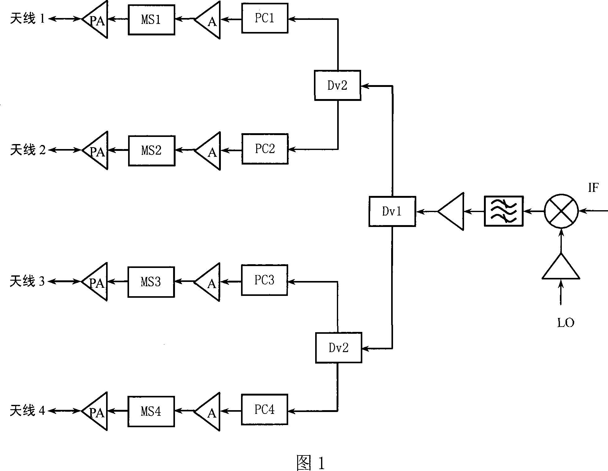
[0004] In order to realize the integrated and miniaturized design of the millimeter-wave active transmitting antenna, based on the existing integration level, the transmitting module adopts the multi-chip assembly technology based on MMIC technology, and the transmitting module composed of cascaded multi-stage amplifiers in this implementation scheme The channel is relatively easy to ensure the consistency of the transmitted signal amplitude, but the phase consistency is difficult to achieve. At the same time, it is limited by the integration and miniaturization design requirements and cannot add a phase shifter. Therefore, the phase error of the transmitted signal is large, and it is applied to active transmission. The antenna will seriously affect the radiation pattern of the active antenna

Method used


Image

  • Millimeter wave integration multichannel active transmitting antenna and phase compensation method thereof
  • Millimeter wave integration multichannel active transmitting antenna and phase compensation method thereof
  • Millimeter wave integration multichannel active transmitting antenna and phase compensation method thereof

Examples


Embodiment 1

[0048] Taking the phase error of 95 degrees as an example to introduce the operation steps of the active transmitting antenna phase error compensation proposed by the present invention:

[0049] 1. Use a vector network analyzer to measure the phase error of the transmitting channel, so as to obtain the phase error θ between the two channels of the active transmitting antenna when the operating frequency is 33GHz 1 is 95 degrees.

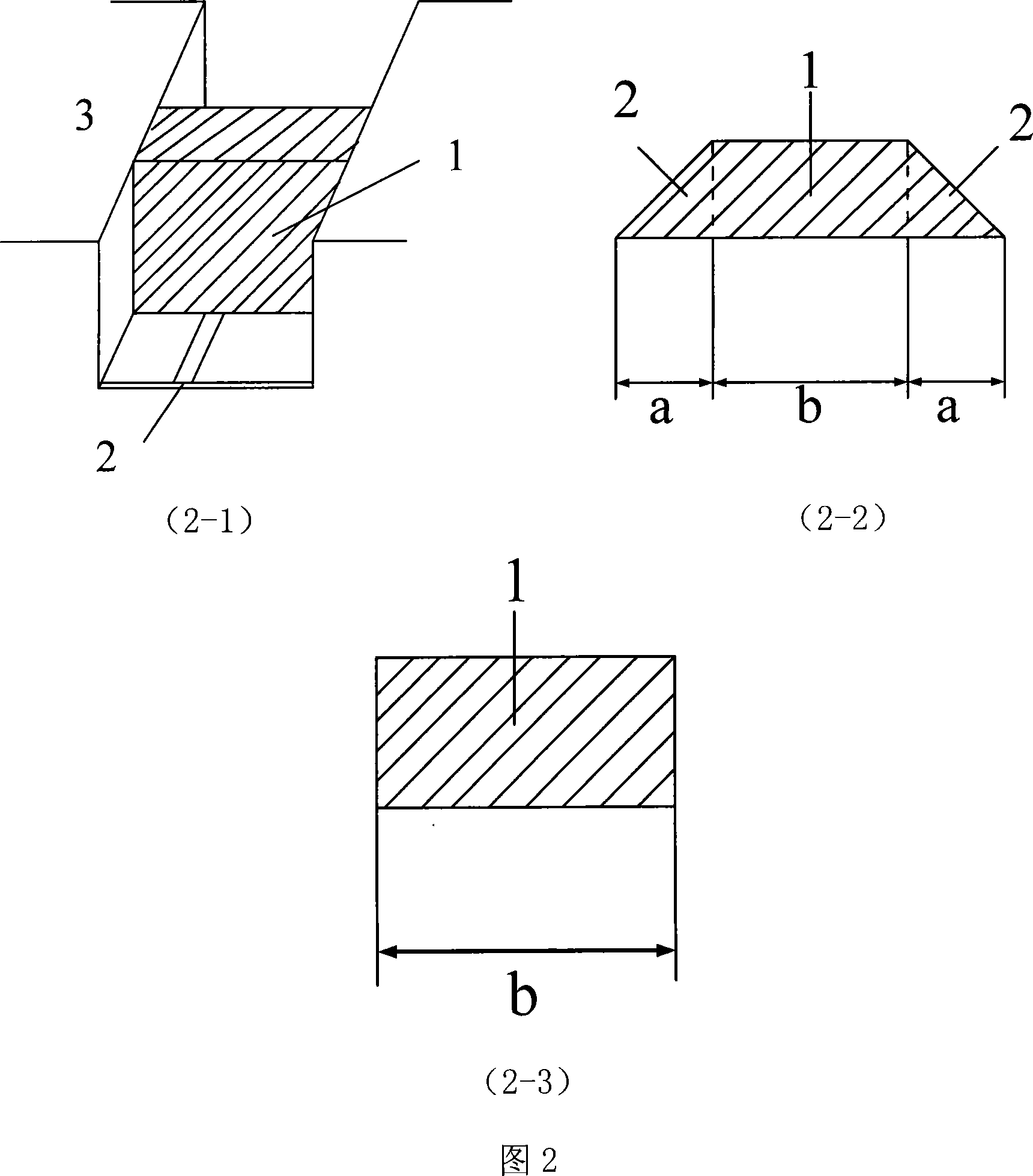
[0050] 2. Choose a regular cuboid ceramic medium to load, the thickness is 0.5 mm, the width is equal to that of the shielding cavity and the side wall is in full contact with the metal side wall of the shielding cavity. The height of the air shielding cavity is 3 mm, which is convenient for calculation and selection of a cuboid structure without a transition section . At this time, the equivalent dielectric constant ε of the structure re is 1.583.

[0051] 3. Determine the length l of the phase compensation section according to formula (1) 1 , p...

Embodiment 2

[0057] Taking the phase error of 50 degrees as an example to introduce the phase error compensation operation steps of the active transmitting antenna proposed by the present invention, the specific operation steps are the same as those in Embodiment 1, except that the length of the compensation section is different. Suppose the phase error θ 2 λ is 50 degrees and the operating frequency is 33GHz 0 9.09 mm, equivalent dielectric constant ε re is 1.583, and these known parameters are substituted into formula (1) to get

[0058] (4)

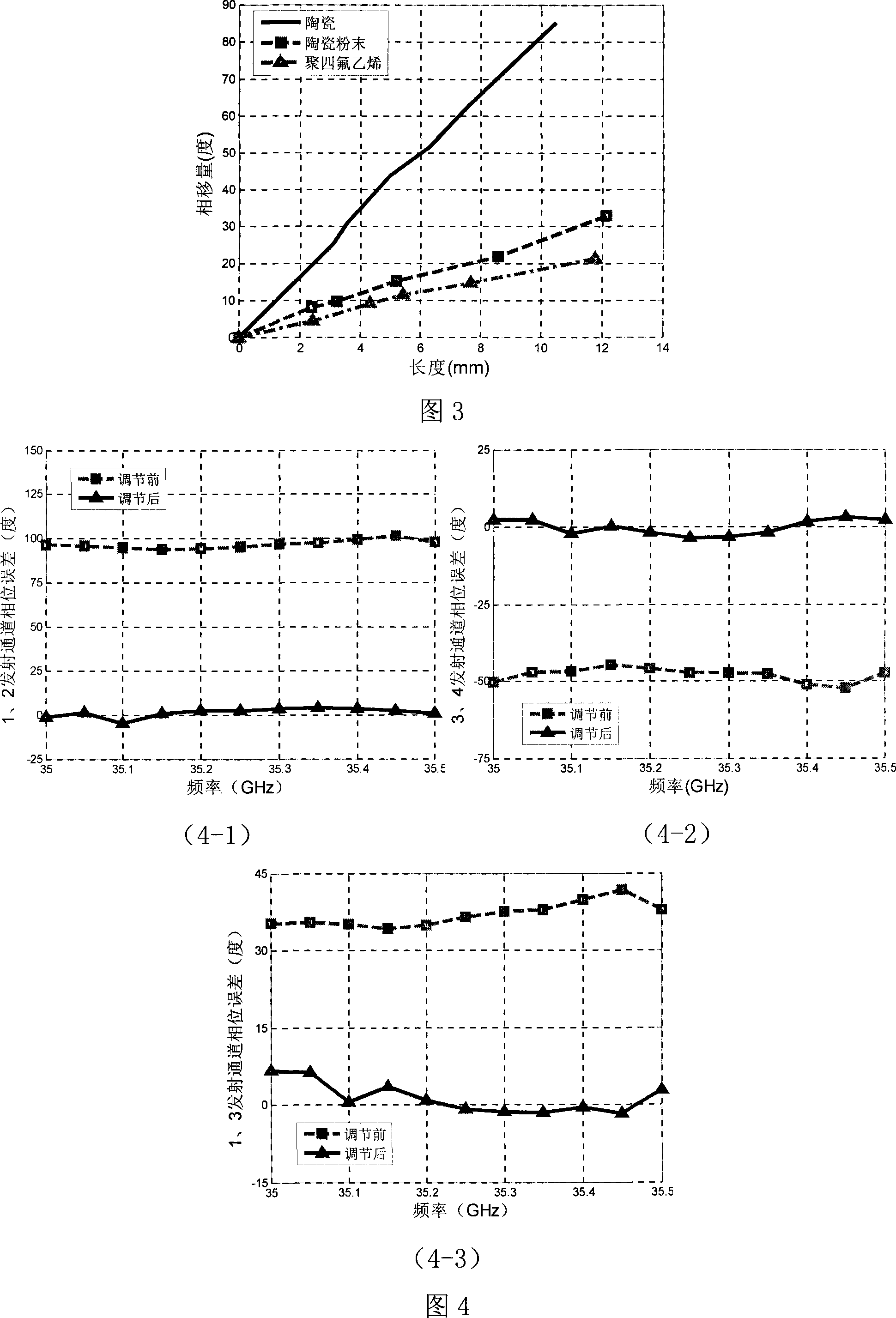
[0059] Perform phase compensation according to the operation steps in Embodiment 1, Figure 4-2 It is the actual measurement result of the phase error before and after compensation by using the medium-loaded microstrip line method proposed by the present invention when the channel phase error is 50 degrees. After compensation, the phase error of the channel with an operating frequency of 33 GHz is 2.21 degrees.

Embodiment 3

[0061] Taking the phase error of 35 degrees as an example to introduce the phase error compensation operation steps of the active transmitting antenna proposed by the present invention, the specific operation steps are the same as those in Embodiment 1, except that the length of the compensation section is different. Suppose the phase error θ 3 is 35 degrees, when the operating frequency is 33GHz λ 0 is 8.57 mm, the equivalent dielectric constant ε re is 1.583, and these known parameters are substituted into formula (1) to get

[0062] (5)

[0063] Perform phase compensation according to the operation steps in Embodiment 1, Figure 4-3 It is the actual measurement result of the phase error before and after compensation using the medium-loaded microstrip line method proposed by the present invention when the channel phase error is 35 degrees. After compensation, the phase error of the channel with an operating frequency of 33 GHz is 4.57 degrees.


PUM


Abstract

The invention provides an integrated millimeter-wave multi-passage active transmitting antenna device and a phase compensation method of the same, wherein the antenna device comprises a millimeter-wave arrayed antenna and a multi-passage active transmitting module, the compensation method belongs to the active antenna technical field and comprises a micro-strip line, a loading medium and a metal box body. The antenna device adopts an integrated structure, and the active transmitting antenna device is not provided with any active phase-shifting apparatus inside. The phase compensation method between passages is to use the micro-strip line which plays a cascade role at a pre-stage input port of a power amplifier to load a medium with a high dielectric constant. Phase error compensation in arange between zero and three hundred and sixty degrees can be realized by selecting different loading mediums without affecting the uniformity of amplitude. The antenna device and the phase compensation method have the advantages of simple debugging, exquisite design and miniaturization, etc., and is an antenna device and phase compensation method with strong operability and practicality.

Description

technical field [0001] The invention belongs to the technical field of active antennas. Background technique [0002] The active transmitting antenna is composed of the direct connection between the active transmitting module and the antenna unit. It has the advantages of small size, light weight, and compact structure. It has broad application prospects in the fields of mobile communication, military detection, and electronic countermeasures. In recent years, with the rapid development of monolithic microwave integrated circuit (MMIC), spatial power combining technology and millimeter-wave full-plane integration technology, the millimeter-wave active transmitting antenna technology has been promoted to mature, and the millimeter-wave active transmitting antenna has become a research topic. hotspots. However, independent active transmitting antennas cannot realize beamforming and beam electronic scanning, so multi-channel active transmitting antennas have more profound acad...

Claims


Application Information

Patent Timeline
Patent Type & Authority Patents(China)
IPC IPC(8): H01Q23/00H01Q21/00H01Q13/00H01Q3/34
Inventor 孙厚军于伟华杨怀志吕昕张伟徐强陈亚萍
Owner BEIJING INSTITUTE OF TECHNOLOGYGY
Learn More