System and method for obtaining radiation characteristics of built-in antenna in mobile communication terminal

a built-in antenna and antenna technology, applied in the field of mobile communication systems, can solve the problems of increasing the size of the main body case, limiting the frequency and level of emi signals radiated outwardly from the interior of an electronic product, and affecting the operation of the internal components of the terminal,

Inactive Publication Date: 2010-02-23
LG ELECTRONICS INC
View PDF33 Cites 8 Cited by
  • Summary
  • Abstract
  • Description
  • Claims
  • Application Information

AI Technical Summary

Benefits of technology

[0014]Another object of the present invention is to provide a mobile terminal having a built-in antenna at a main PCB which is also compact in size.
[0016]Another object of the present invention is to set a ground region and position of an FPCB connector in a folder and a main body to maximize wireless performance characteristics of a built-in antenna.
[0017]To achieve at least the above objects and advantages in whole or part, the present invention provides in accordance with one embodiment a system and method for enhancing radiation gain of an antenna in a mobile communication terminal. This is accomplished by forming an antenna at a main PCB of a hinge part of the mobile terminal. Also, an electromagnetic interference (EMI) shielding region is set at an upper portion of a main body part of the terminal in order to obtain a desired radiation gain of the antenna. Through this design, use of metallic material and EMI spraying is advantageously avoided at a region of the main body part included in the EMI shielding region.
[0019]Also, if the mobile terminal is a folder type terminal, use of a metallic material and EMI spraying are preferably avoided at the region of a folder part included in the EMI shielding region when the folder is closed. For this purpose, a PCB ground is removed from the folder part and an FPCB connector is moved from the folder part to a position opposite of the built-in antenna.
[0022]In accordance with another embodiment, the present invention provides a mobile terminal which includes: a main body part accommodating a main printed circuit board (PCB), a folder part hinged at the main body part; a built-in antenna assembled at one side of the main PCB, and an EMI shielding region positioned at an upper side of the main body part preferably where a built-in antenna is installed. The built-in antenna may be positioned at a hinge part, and the EMI shielding region may be a region where EMI spraying and use of a metallic material are avoided.
[0024]In order to prevent the built-in antenna from being affected when the folder part is closed, a PCB ground may be removed from the folder part and the flexible PCB (FPCB) connector may be moved to a position opposite the built-in antenna.

Problems solved by technology

EMI signals in particular have a strong potential to affect the operation of the internal components of the terminal, including its electronic device packages.
Consequently, the frequency and level of EMI signals radiated outwardly from the interior of an electronic product are often limited.
This inevitably increases the size of the main body case, which diminishes the ability to make the terminal compact in size.

Method used


Image

  • System and method for obtaining radiation characteristics of built-in antenna in mobile communication terminal
  • System and method for obtaining radiation characteristics of built-in antenna in mobile communication terminal
  • System and method for obtaining radiation characteristics of built-in antenna in mobile communication terminal

Examples


Embodiment Construction

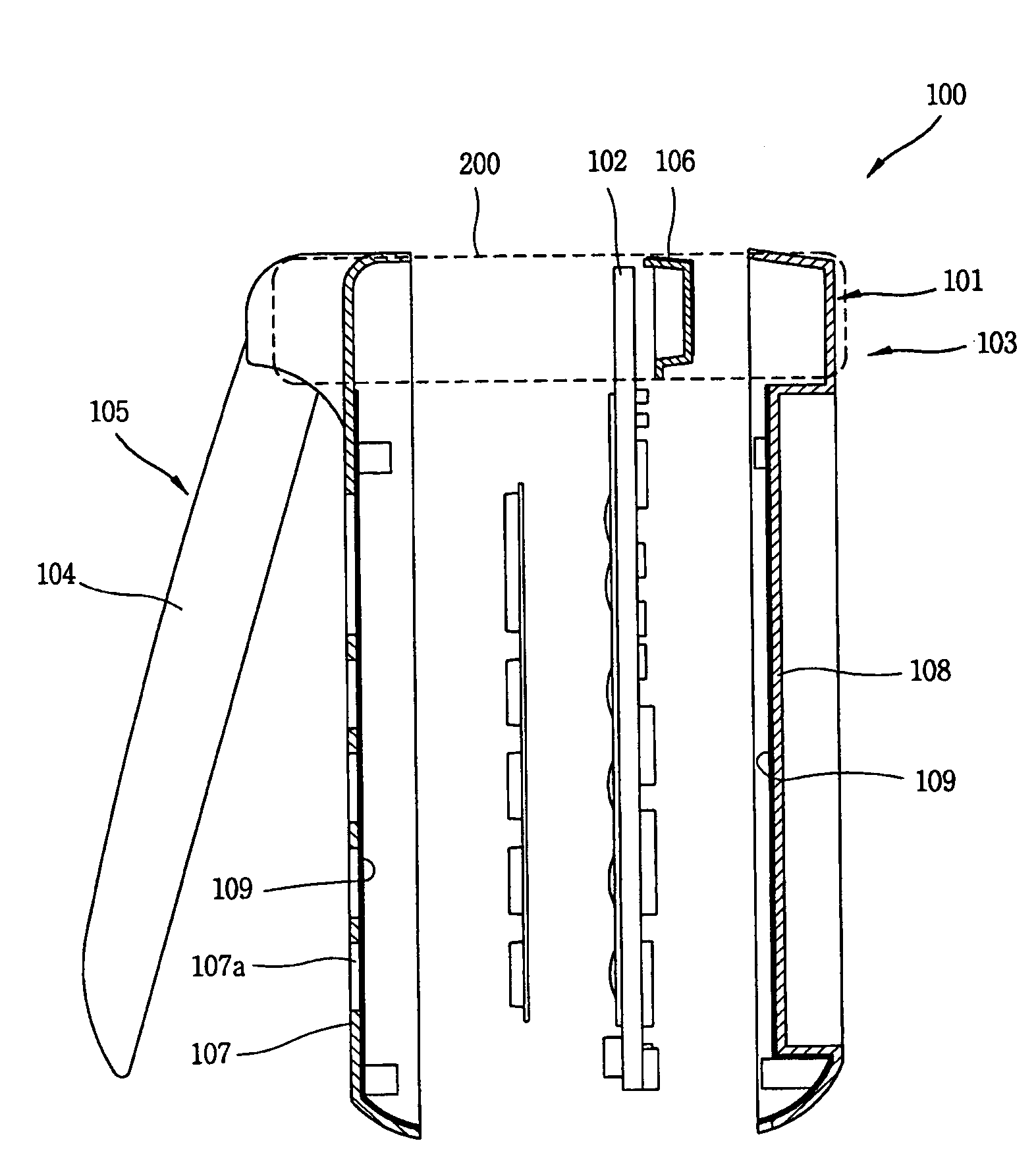
[0034]The present invention may be adopted to design a built-in antenna of a mobile terminal including but not limited to a folder-type mobile terminal. In addition, in accordance with at least one embodiment the present invention may increase and / or achieve a desired level of performance of a terminal having a built-in antenna installed at one side of an upper end portion of a main PCB.

[0035]In terms of performance, the present invention may implement wireless characteristics suitable for a built-in antenna product of a folder-type mobile terminal, specifically with respect to the relationships among radiation performance of the built-in antenna, EMI, and ground. For this purpose, a predetermined range of a main body part (including a hinge part) where the built-in antenna is installed may be set as an electromagnetic interference (EMI) shielding region in order to obtain a desired radiation gain of the antenna. In addition, to maximize the radiation gain of the antenna, an innovat...


PUM


Abstract

A mobile terminal has an electromagnetic interference (EMI) shielding region set at an upper side of a main body part where an internal antenna is mounted. The internal antenna may be mounted on a main printed circuit board (PCB) in order to obtain a desired radiation gain. Such a shielding region alleviates the need to use metallic shielding material or EMI spraying throughout many parts of the terminal. In addition, in order to maximize wireless characteristics of the built-in antenna, a PCB ground is removed from a folder part and a FPCB connector is moved to a position along a side of a terminal display. With this structure, degradation of radiation characteristics of the antenna due to metal components installed around the built-in antenna can be prevented, and thus a stable radiation gain of the terminal antenna can be obtained.

Description

BACKGROUND OF THE INVENTION[0001]1. Field of the Invention[0002]The present invention generally relates to mobile communication systems, and more particularly to a system and method for obtaining radiation gain characteristics of a built-in antenna in a mobile communication terminal.[0003]2. Background of the Related Art[0004]A mobile communication terminal (referred to as ‘terminal’, hereinafter) may generally be regarded as any portable device that transmits and receives voice, character, and / or image information with other terminals or devices.[0005]Lately, mobile terminals are being provided with a wireless data service having a reinforced multimedia function. Also, recent trends require that mobile terminals become more compact and light-weight for carrying convenience. To meet these requirements, terminals are now using internal instead of external antennas. Internal antennas can be used to support Bluetooth, wireless LAN, GSM, CDMA and other communication protocols and format...

Claims


Application Information

Patent Timeline
Patent Type & Authority Patents(United States)
IPC IPC(8): H04M1/00H01Q1/24H01Q19/02H01Q1/52
CPCH01Q1/243H01Q1/526H01Q1/24
Inventor PARK, BYUNG-DUCKKIM, SOO-CHEOUL
Owner LG ELECTRONICS INC
Why Eureka
Try Eureka