In-vehicle antenna apparatus

a technology for antennas and vehicles, applied in the direction of antennas, antenna details, antenna adaptation in movable bodies, etc., can solve the problems of narrow angle of view of vehicle occupants including drivers, weakening directional characteristics, and reducing the radiation gain in the incoming direction of tuned radio waves, so as to facilitate the assembly process, facilitate the installation, and facilitate the effect of attachmen

Inactive Publication Date: 2006-03-02
ALPS ALPINE CO LTD +2
View PDF2 Cites 7 Cited by
  • Summary
  • Abstract
  • Description
  • Claims
  • Application Information

AI Technical Summary

Benefits of technology

[0013] Furthermore, the in-vehicle antenna apparatus may further include a base plate fixed on the inner surface of the sheet of glass; and a housing that houses the circuit substrate. The housing is preferably mounted on the inner surface of the sheet of glass via the base plate. According to this structure, since the housing can be easily attached to and detached from the sheet of glass, it is not necessary to perform complicated processes, such as demounting and remounting processes, when the circuit substrate is to be inspected or replaced with a new one. In this case, the housing preferably includes a sheet-metal frame body that surrounds and supports the circuit substrate and that is fixed to the base plate in a detachable manner; and a sheet-metal cover that engages with the frame body so as to cover the first surface of the circuit substrate. Accordingly, since the circuit substrate can be readily installed in the frame body before the engagement process of the cover, the overall assembly process is simplified.
[0014] According to the in-vehicle antenna apparatus of the present invention, the patch-like radiation conductor on the inner surface of the sheet of glass is connected with the electric circuit on the first surface of the circuit substrate, and the second ground conductor on the second surface of the circuit substrate is opposed to and disposed separate from the radiation conductor so as to function as the radio-wave reflective surface. Thus, the second ground conductor for the electric circuit on the circuit substrate functions both as a part of the first ground conductor for the radiation conductor and as the radio-wave reflective surface for improving the radiation gain in the incoming direction of a tuned radio-wave. Accordingly, an in-vehicle antenna apparatus that is compact in size and that achieves a high radiation gain is achieved.

Problems solved by technology

This means that a ground conductor with a large dimension must be provided on the sheet of glass, such as rear glass or front glass, and is thus problematic in that such a large-size ground conductor may narrow the angle of view for vehicle occupants including a driver.
This weakens the directional characteristics for intensely emitting radio-waves outward from the sheet of glass, and is thus problematic in that the radiation gain in the incoming direction of a tuned radio-wave becomes lower.

Method used


Image

  • In-vehicle antenna apparatus
  • In-vehicle antenna apparatus
  • In-vehicle antenna apparatus

Examples


Embodiment Construction

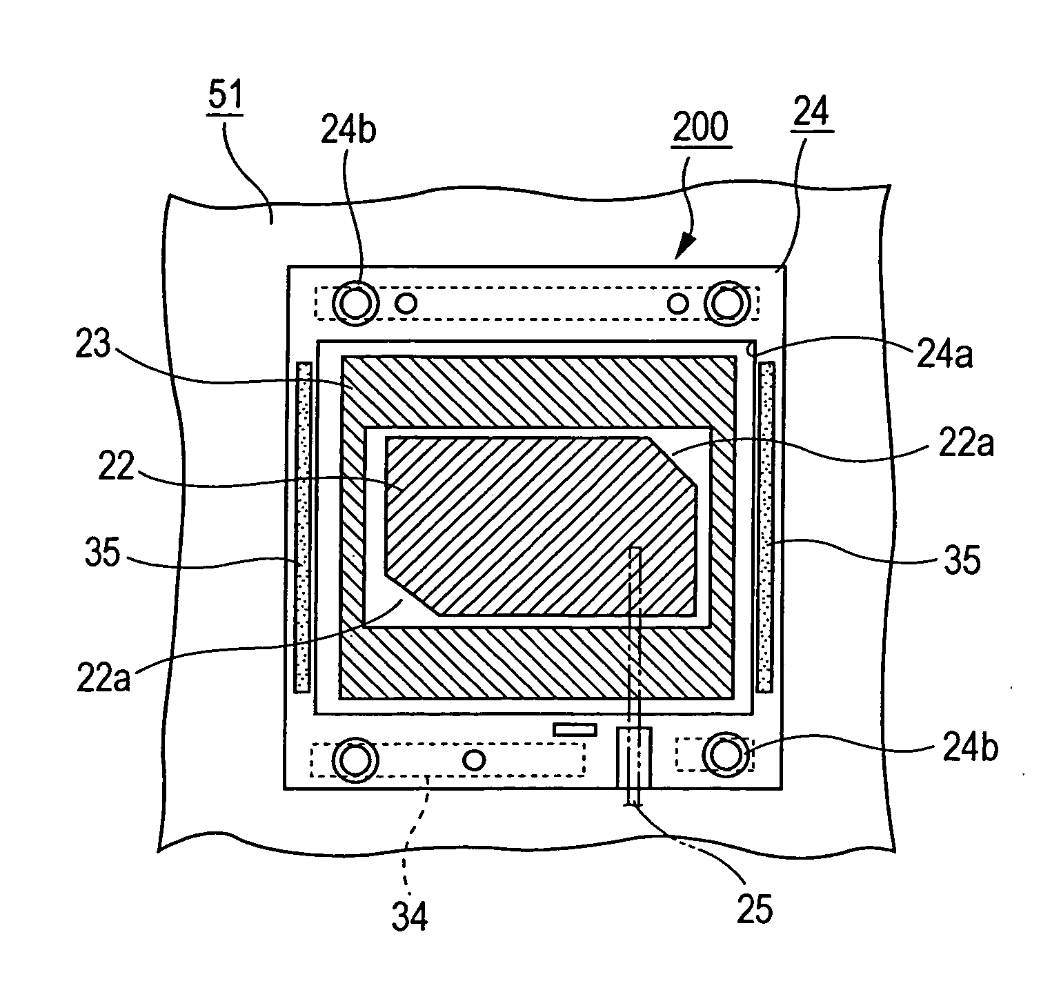
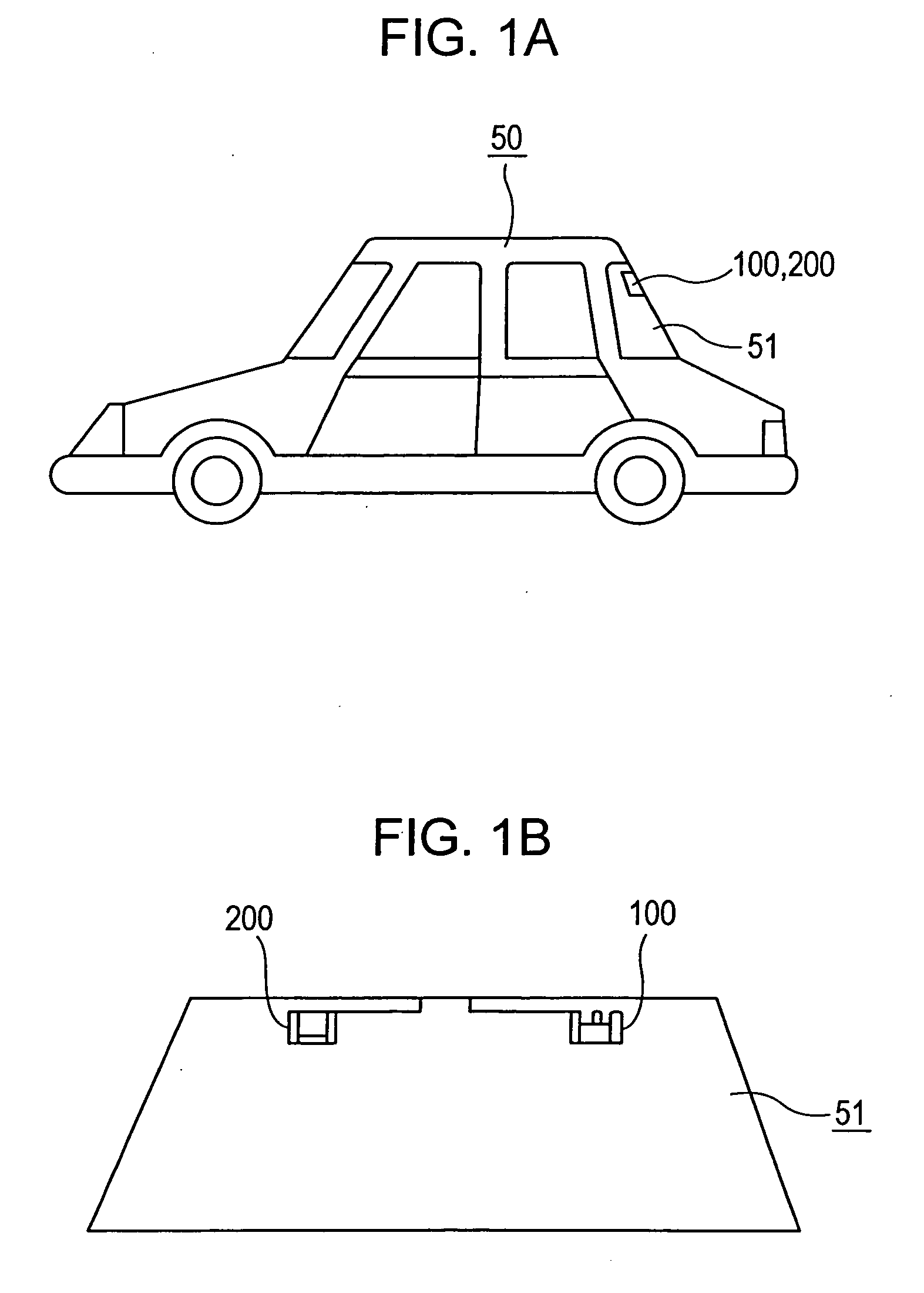
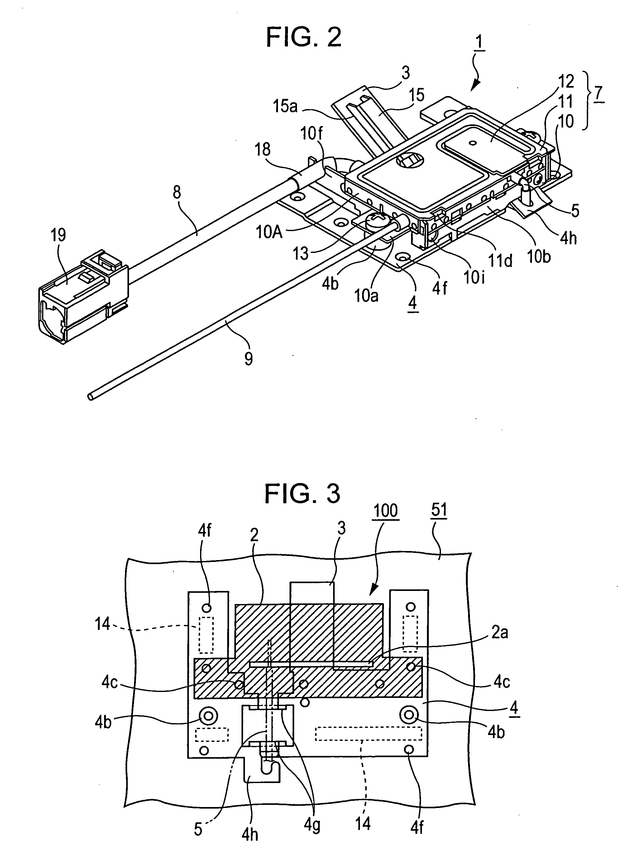
[0030] Embodiments of the present invention will now be described with reference to the drawings. FIGS. 1A and 1B are schematic views illustrating a mounting position of an in-vehicle antenna apparatus according to an embodiment of the present invention. Specifically, FIG. 1A is a side view of a vehicle, and FIG. 1B is a front view of rear glass as viewed from the inside of the vehicle. FIGS. 2 to 8 illustrate a ground-based antenna device 100 included the in-vehicle antenna apparatus. FIG. 2 is a perspective view of an electronic circuit unit 1 provided in the ground-based antenna device 100. FIG. 3 is a schematic view illustrating a positional relationship between a base plate 4 of the electronic circuit unit 1 and a radiation conductor 2. FIG. 4 is an exploded perspective view of the electronic circuit unit 1. FIG. 5 is a plan view of the electronic circuit unit 1. FIG. 6 is a bottom view of the electronic circuit unit 1. FIG. 7 is a side view of the electronic circuit unit 1. FI...


PUM


Abstract

Rear glass is provided with a patch-like radiation conductor and a first ground conductor surrounding the patch-like radiation conductor. An electronic circuit unit includes a base plate fixed on the rear glass; a frame body which houses a circuit substrate and is fixed on the base plate; and a cover for covering the frame body. One surface of the circuit substrate defines a component-holding surface which is connected with a second end of a feeder cable connected with the radiation conductor and the first ground conductor. The other surface of the circuit substrate is provided with a second ground conductor to function as a radio-wave reflective surface. The radio-wave reflective surface faces the radiation conductor and the first ground conductor disposed on the rear glass such that the radio-wave reflective surface is separated from the radiation conductor and the first ground conductor by a predetermined distance.

Description

BACKGROUND OF THE INVENTION [0001] This application claims the benefit of Japanese Patent Application No. 2004-188728 filed in Japan on Jun. 25, 2004, which is hereby incorporated by reference. [0002] 1. Field of the Invention [0003] The present invention relates to an in-vehicle antenna apparatus mounted on a windowpane of a vehicle, such as an automobile, and particularly, to an in-vehicle antenna apparatus provided with a patch-like radiation conductor disposed on an inner surface of a windowpane. [0004] 2. Description of the Related Art [0005] Japanese Unexamined Patent Application Publication No. 2002-252520 (p. 3 to p. 5, FIG. 1) discloses an example of a conventional in-vehicle antenna apparatus provided with a radiation conductor and a ground conductor disposed on an inner surface of rear glass or front glass of a vehicle. The radiation conductor and the ground conductor are connected to a circuit substrate via a coaxial cable such that the in-vehicle antenna apparatus is ca...

Claims


Application Information

Patent Timeline
Patent Type & Authority Applications(United States)
IPC IPC(8): H01Q1/32H01Q1/12H01Q1/40
CPCH01Q1/1271H01Q1/40H01Q1/32
Inventor IKEDA, TOMOKISHIRAISHI, NAOFUMINAKAGAWA, MASASHIKOMATSU, SATORUFUKUMARU, TOMOYUKIOSHIMA, HIDEAKIIIJIMA, HIROSHI
Owner ALPS ALPINE CO LTD
Why Eureka
Try Eureka