Conformal surface wave antenna based on holographic metasurface

A surface wave and metasurface technology, applied in conformal surface wave antennas, aircraft systems and communication systems, can solve problems such as directional radiation, achieve the effects of diffraction propagation and increase radiation gain

Active Publication Date: 2019-07-12
XIDIAN UNIV
View PDF4 Cites 8 Cited by
  • Summary
  • Abstract
  • Description
  • Claims
  • Application Information

AI Technical Summary

Problems solved by technology

[0005] To sum up, the existing research has achieved the design of surface wave antennas in specific scenarios, but only for a single plane or curved surface conformal structure. Due to their respective limitations, they cannot solve the problem of electromagnetic waves propagating on a plane. Diffraction propagation after the curved surface protrudes and produces directional radiation in the end-fire direction

Method used


Image

  • Conformal surface wave antenna based on holographic metasurface
  • Conformal surface wave antenna based on holographic metasurface
  • Conformal surface wave antenna based on holographic metasurface

Examples


Embodiment 1

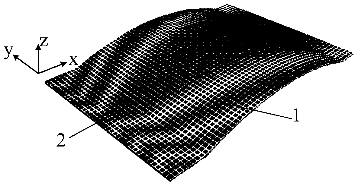
[0035] Embodiment 1. In this embodiment, the radius of curvature of the cylindrical curved surface in the middle part of the holographic impedance surface 1 is R=9λ, and the angle of the center of the circle is Φ=43°, where λ is the wavelength corresponding to the working frequency of 15 GHz. The cylindrical curved surface structure can also realize the diffraction propagation of the surface wave while realizing the modulation of the surface wave.

[0036] refer to figure 1 , the present invention includes a holographic impedance surface 1 and a monopole feed 2, wherein:

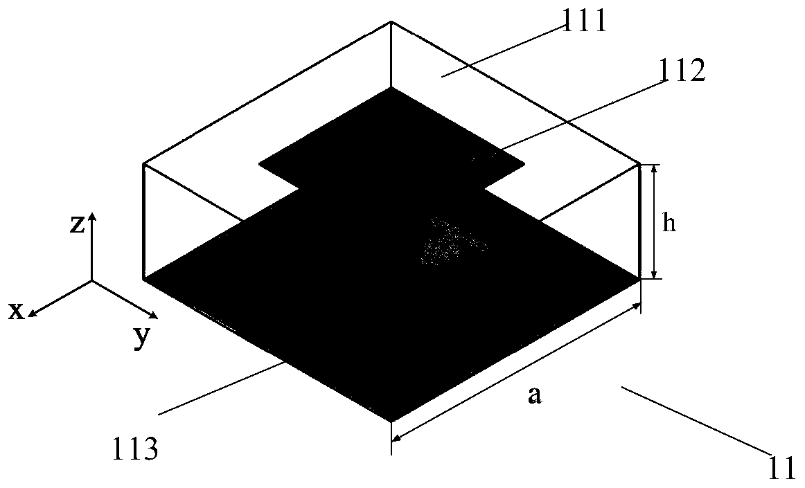
[0037] The holographic impedance surface 1 includes m×n periodically arranged impedance surface units 11, m=85, n=73, and the structure of the impedance surface unit 11 is as follows image 3 As shown, it includes a dielectric plate 111, a square metal patch 112 printed on the center of the upper surface of the dielectric plate 111, and a metal floor 113 on the lower surface. The side length a of the dielec...

Embodiment 2

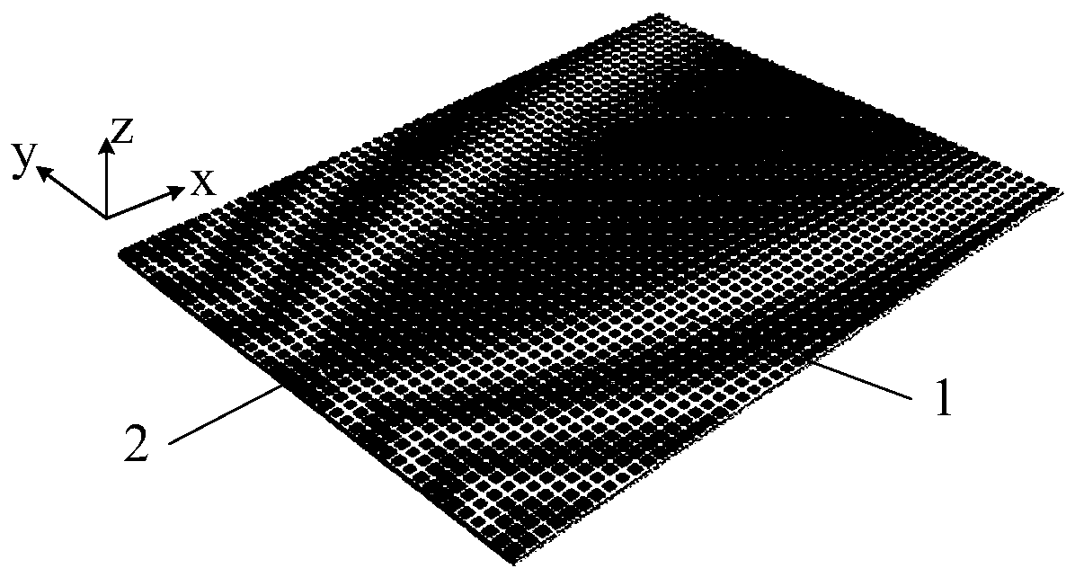
[0058] Embodiment 2, this embodiment is a planar structure, that is, the radius of curvature R of the cylindrical curved surface in the middle part of Embodiment 1 tends to infinity, and the rest of the structure is the same as Embodiment 1, which is a planar structure surface wave antenna for realizing end-fire radiation characteristics .

[0059] refer to figure 2 , the length of the holographic impedance surface 1 along the x-axis is 255 mm, and the length along the y-axis is 220 mm. The coordinates of the impedance surface unit 11 along the coordinate x vary in [-30mm, 225mm], and the coordinate y varies between [-30mm, 225mm]. -110mm, 110mm], the range of change along the coordinate z is [0mm, 1.5mm].

[0060] The interferogram distribution based on the holographic principle, its corresponding reference wave is the cylindrical surface wave produced by the monopole feed source 2, the corresponding target wave is the radiation plane wave on the end-fire direction of the h...


PUM


Abstract

The invention provides a conformal surface wave antenna based on a holographic metasurface. The conformal surface wave antenna comprises a monopole feed source and a holographic impedance surface, theholographic impedance surface comprises m*n periodically arranged impedance surface units, each impedance surface unit comprises a dielectric plate, a square metal patch printed at the center position of the upper surface of the dielectric plate and a metal floor arranged at the lower surface of the dielectric plate, the surface impedance of each impedance surface unit is distributed based on theinterference pattern of a holographic principle, the reference waves corresponding to the distribution of the interference patterns are cylindrical surface waves generated by the monopole feed source, and a target wave is a radiation plane wave in the endfire direction of the holographic impedance surface. Directed radiation is achieved in the endfire direction of the conformal surface wave antenna prior to generation of the cylindrical surface waves, which are subjected to impedance modulation of the holographic impedance surface, by employing the monopole feed source to form a flat plane wave, and when a conformal surface wave antenna meets a curved surface bulge, diffraction propagation of the surface wave can be achieved.

Description

technical field [0001] The invention belongs to the technical field of antennas, and relates to a conformal surface wave antenna, in particular to a conformal surface wave antenna based on a holographic principle and an artificial impedance surface, which can be used in aircraft systems and communication systems. [0002] technical background [0003] Surface wave antennas based on artificial electromagnetic structures are easy to install on various surfaces because of their low profile, small volume, and low air resistance, so they can be well used as transmitting or receiving antennas for millimeter wave communication systems and are widely used In aircraft systems and communication systems. [0004] Surface wave antennas based on artificial electromagnetic structures in existing research involve planar structures and curved surface conformal structures, which can achieve end-fire or edge-fire radiation. For example, in 2014, in his master's thesis titled "Design of a New ...

Claims


Application Information

Patent Timeline
Patent Type & Authority Applications(China)
IPC IPC(8): H01Q19/02H01Q15/00H01Q9/30H01Q1/50
CPCH01Q1/50H01Q9/30H01Q15/0086H01Q19/02
Inventor 杨锐解萌
Owner XIDIAN UNIV
Why Eureka
Try Eureka