
Ladle hydraulic slide runner glidingly stroke converting method

A sliding nozzle and conversion method technology, which is applied in the direction of casting molten material container, metal processing equipment, casting equipment, etc., can solve the problems of sliding nozzle flow control failure, production accidents, reduce the safety factor of sliding nozzle, etc., and achieve the purpose of increasing the continuous use of sliding plates Effect

Inactive Publication Date: 2011-02-16
SHANDONG IRON & STEEL CO LTD
View PDF0 Cites 0 Cited by
  • Summary
  • Abstract
  • Description
  • Claims
  • Application Information

AI Technical Summary

Problems solved by technology

However, with the high-efficiency transformation of the continuous casting machine and the increase of the casting speed, the inner diameter of the sliding nozzle must be increased. If the sliding stroke of the sliding plate is not increased at the same time, the safety factor of the effective flow control of the sliding nozzle will inevitably be reduced, resulting in Flow control failure, causing production accidents

Method used


Image

  • Ladle hydraulic slide runner glidingly stroke converting method
  • Ladle hydraulic slide runner glidingly stroke converting method
  • Ladle hydraulic slide runner glidingly stroke converting method

Examples


Embodiment Construction

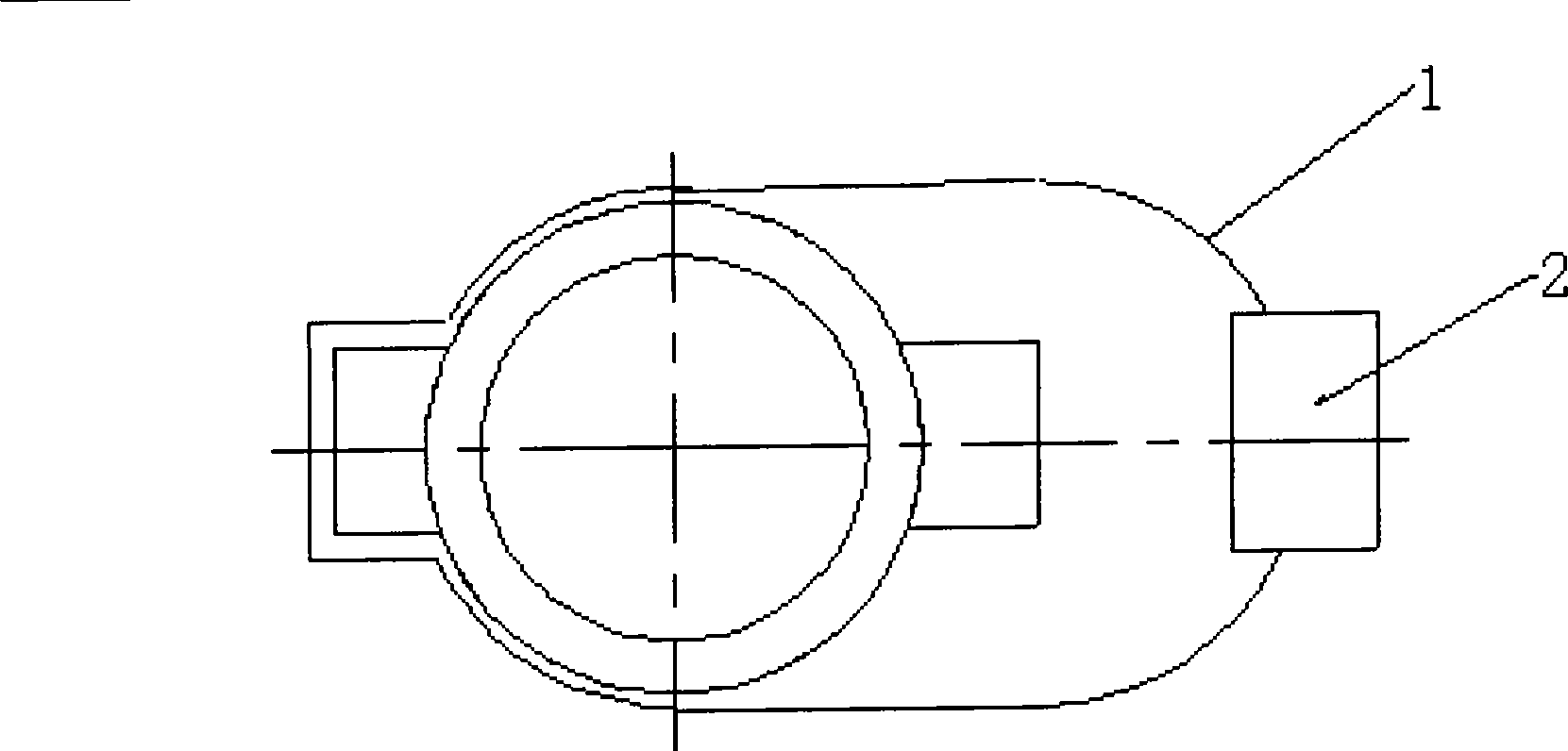
[0018] 1) Temporarily weld a stroke control module on the limit control part of the switch mold frame of the sliding nozzle mechanism, so that the sliding stroke is temporarily adjusted from the designed stroke to the old stroke before the transformation;

[0019] The sliding stroke is increased from 165mm to 200mm, and a stroke control module with a width of 35mm is temporarily welded to the limit control part of the switch mold frame of the sliding nozzle mechanism, so that the sliding stroke of the slide plate is temporarily adjusted from the designed 200mm to 165mm.

[0020] 2) After the transformation of the sliding stroke of all ladle sliding nozzle mechanisms is completed, cut off the stroke control module for the ladle that is not used for online turnover, so that the sliding stroke can be restored to the designed stroke, and replace the cylinder stroke of the ladle nozzle preparation area from the old stroke cylinder to Design stroke cylinder, cylinder stroke changed f...


PUM


Abstract

A sliding stroke conversion method of a hydraulic ladle sliding nozzle, which belongs to the technology field of hydraulic ladle sliding nozzle continuous casting device, and comprises the following steps: temporarily welding a stroke control module at a position-limiting control section of open / close mold frame of the sliding nozzle mechanism to adjust the sliding stroke from a design stroke to an old stroke; cutting off a temporarily new stroke position limiting control module of ladles that are not circularly used online when completing the sliding stroke reconstruction of the ladle sliding nozzle mechanism to recover the sliding stroke to the design stroke; replacing the oil cylinder stroke in a ladle nozzle preparation region to change an old stroke oil cylinder into a design stroke oil cylinder; adjusting the stroke of the oil cylinder for ladle free-opening of a continuous casting machine by the following steps: pulling the shutoff stroke of a ladle mechanism to the old stroke by a special device for extending the stroke of the oil cylinder, taking off the special device, re-hanging the oil cylinder with the old stroke, and operating normally; and changing the oil cylinder for ladle free-opening of the continuous casting machine into oil cylinders with the design stroke when the temporarily position limiting control modules of all ladle mechanisms are cut off, thus achieving the sliding stroke conversion of all ladle sliding nozzles.

Description

technical field [0001] The invention relates to a sliding stroke conversion method of a ladle hydraulic sliding nozzle, which belongs to the technical field of continuous casting ladle hydraulic sliding nozzle devices in iron and steel metallurgy. Background technique [0002] In recent years, with the high-efficiency transformation of steelmaking and continuous casting equipment and the popularization of new metallurgical technologies, in order to meet the needs of fast-paced production and continuous cost reduction, it is necessary to realize the continuous use of multiple furnaces of slide plates and speed up the turnover of ladles. At the same time, with the development and production of new low-silicon and low-carbon steel types, more and more stringent requirements are put forward for the ladle sliding nozzle, and ensuring the effective flow control of the ladle sliding nozzle has become a new research topic. At present, the technical transformation of multiple furnace...

Claims


Application Information

Patent Timeline
Patent Type & Authority Patents(China)
IPC IPC(8): B22D41/38
Inventor 吕铭武光君李洪建王学新冯启超
Owner SHANDONG IRON & STEEL CO LTD
Learn More