
lifting column

A sliding element and sliding structure technology, applied in the field of lifting columns, can solve the problems of large gaps and increased costs

Active Publication Date: 2020-11-03
EWELLIX AB
View PDF10 Cites 0 Cited by
  • Summary
  • Abstract
  • Description
  • Claims
  • Application Information

AI Technical Summary

Problems solved by technology

The gap between the two pipe pieces can thus be relatively large
In addition, in some lifting columns the effort for selecting the plain bearing of the required thickness and correspondingly arranging the plain bearing is thus increased, even if several plain bearings belong to one sliding system

Method used


Image

  • lifting column
  • lifting column
  • lifting column

Examples


Embodiment Construction

[0024] In the following description of the figures, identical or functionally identical components are provided with the same reference symbols. In addition, generalized reference numbers can be used for components and objects which appear several times in the exemplary embodiments or figures, but which are described jointly with respect to one or more features. Parts or objects described with the same or general reference signs can be implemented identically with regard to individual, multiple or all features (eg in terms of dimensions), but can also differ if necessary, unless otherwise explained or illustrated by the description. implemented.

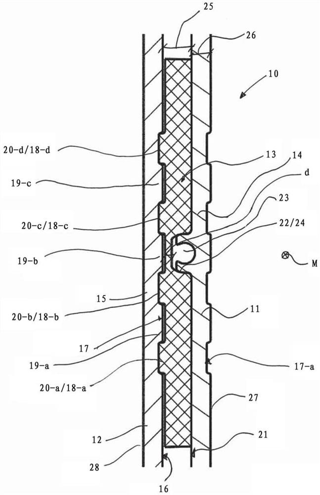
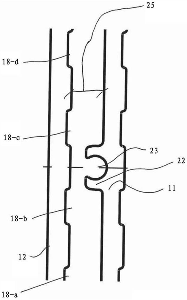
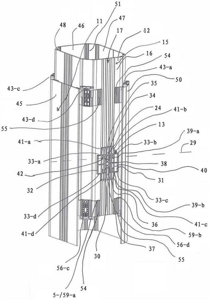
[0025] figure 1 and 2 A schematic cross-section of the lifting column 10 is shown in different cut planes, wherein figure 1 cut through the sliding element 13 of the lifting column and figure 2 The tangent plane of extends beyond the sliding element 13. exist image 3 A section 29 can be seen in , which represents figure 1 se...


PUM


Abstract

The invention relates to a lifting column (10), which includes at least one first tube (11) and at least one second tube (12). The second tube is movably arranged in the first tube (11) along the axial direction. . The lifting column (11) also includes at least one sliding element (13) arranged between the first tube (11) and the second tube (12). The sliding element (13) is in direct contact with the first tube (11) and the second tube (12) and is arranged to be axially movable relative to the first tube (11) and the second tube (12).

Description

technical field [0001] The present invention relates to a lifting column. Conventional telescoping columns or lifting columns generally include a drive system, a plurality of telescoping tubulars that slide against each other and a guide system and / or a slide system. Pressure and / or traction can be applied to the pipes by the drive system to move the pipes relative to each other. A stabilization against bending and torsion of the individual pipe parts relative to one another can be achieved in many cases by means of the guide system and / or the sliding system. Background technique [0002] The individual tubes are usually made of metal or, however, can also be made of other materials, on which the individual sliding bearings are fastened as guide and / or sliding systems. One side of a plain bearing slides along the surface of a larger or smaller pipe. In order to overcome torsional forces, some conventional pipes have notches or rails on which sliding bearings fixed to othe...

Claims


Application Information

Patent Timeline
Patent Type & Authority Patents(China)
IPC IPC(8): F16B7/10A47B9/20
CPCA47B9/20F16B7/10F16C29/12F16M11/26A47C3/40A47B2200/002
Inventor A.克里斯滕D.格伯
Owner EWELLIX AB
Learn More