
Dry optical - chemical carbon - dioxide sensor

An optical sensor, carbon dioxide technology, applied in scientific instruments, material analysis by optical means, analysis by chemical reaction of materials, etc., can solve problems such as difficulty in implementing sensor compositions

Inactive Publication Date: 2008-09-03
F HOFFMANN LA ROCHE & CO AG +1
View PDF13 Cites 11 Cited by
  • Summary
  • Abstract
  • Description
  • Claims
  • Application Information

AI Technical Summary

Problems solved by technology

Therefore, optically inert cationic species were replaced by cationic emitters due to unacceptably high baselines [Q + ] would represent a difficult sensor composition

Method used

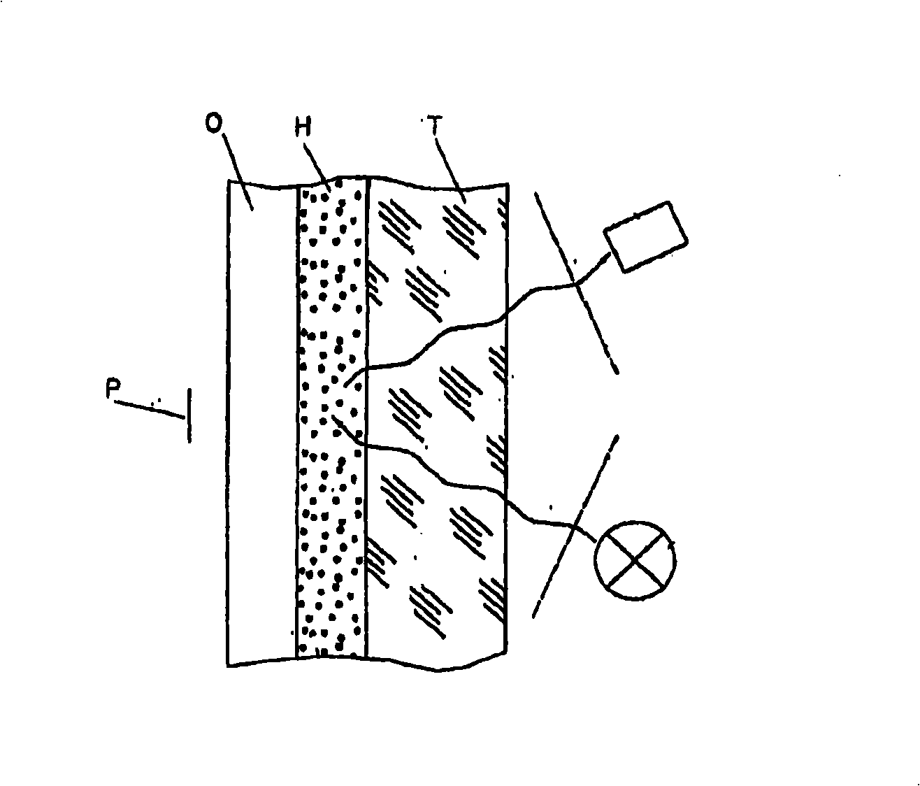
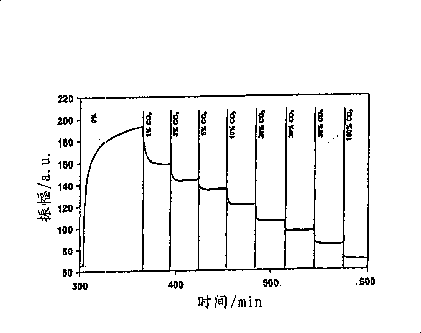
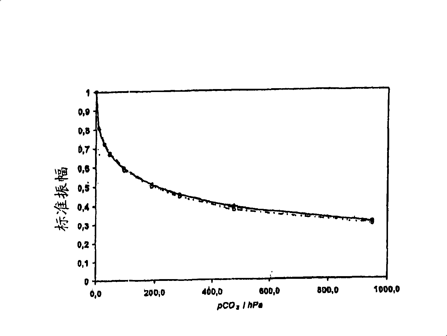

Image

  • Dry optical - chemical carbon - dioxide sensor
  • Dry optical - chemical carbon - dioxide sensor
  • Dry optical - chemical carbon - dioxide sensor

Examples


Embodiment 1

[0093] Example 1: Sensors Comprising Use of Solubilized Metal Cations

[0094] General formulation: ethylcellulose / HPTS tris(K-crown 6) salt / (Z-crown 6) hydroxide / white Teflon overlay (TiO in TeflonAF 2 )

[0095] Solution I: 10mg HPTS

[0096] 34.7mg 18-crown-6

[0097] 955.3mg Methanol

[0098] Solution II: 15.0 mg KOH

[0099] 157.9mg 18-crown-6 (Aldrich 34682)

[0100] 1326.7mg Methanol

[0101] Fabrication of Optical Sensors

[0102] To 1 g of 10% w / w ethylcellulose in toluene / ethanol (4 / 1 v / v) was added 26 mg of solution I. To this mixture was added 56.2 mg of solution II and this casting solution was mixed thoroughly, and the corresponding uniform coating solution was coated on a 125 μm polyester sheet (Mylar foil, Goodfellow ES301425) using a knife coater (Zehntner ZAA2300) , with a wet film thickness of 150 μm. The dried sensor film is translucent. In addition, the sensor membrane was coated with a Teflon layer with a wet film thickness of 150 μm to enhance ...


PUM

PropertyMeasurementUnit
thicknessaaaaaaaaaa

Abstract

A device for determining carbon dioxide in a gaseous or liquid sample, comprises: a polymer matrix and an indicator embedded in the polymer matrix, wherein the indicator comprises a pH-sensitive dye and a metal cation complex, and wherein an anion of the pH-sensitive dye and the metal cation form a salt which is soluble in the polymer matrix.

Description

technical field [0001] The invention relates to a method for measuring carbon dioxide (CO2) in gaseous or liquid samples. 2 ) device and method. In particular, the invention relates to a device for determining the partial pressure of carbon dioxide. Background technique [0002] Carbon dioxide (CO2) in gaseous or liquid samples 2 ) measurements can be deduced from pH measurements, and many measure CO 2 or other sour gas or liquid devices are known in the art. [0003] A photochemical sensor (also known as an optode or optrode) comprises a sensor matrix which is a composition containing an indicator whose optical properties vary with the concentration of a particular analyte contained in the sample. Variety. Such a sensor matrix typically consists of a composition of one or more inorganic and / or organic, preferably polymeric substances, which can be applied on a transparent carrier or substrate, and at least one composition comprising an indicator . The carrier can be ...

Claims


Application Information

Patent Timeline
Patent Type & Authority Applications(China)
IPC IPC(8): G01N21/80G01N33/50
CPCG01N33/004G01N21/783G01N21/80Y10T436/204998G01N2021/773Y02A50/20
Inventor M·J·P·莱纳J·K·图萨I·克利曼特
Owner F HOFFMANN LA ROCHE & CO AG
Learn More