
Automatic flexible chucking tools

A flexible and fixture technology, applied in the field of fixtures, can solve problems such as high requirements for fixtures, difficulty in automatic grasping, shape and position errors of workpieces, etc., to achieve the effect of increasing contact area, compensating shape errors, and reducing damage

Inactive Publication Date: 2008-09-10
天津智通信息系统集成有限公司
View PDF0 Cites 37 Cited by
  • Summary
  • Abstract
  • Description
  • Claims
  • Application Information

AI Technical Summary

Problems solved by technology

However, in some occasions, the requirements for fixtures are very high, such as the handling of sand cores in the foundry industry. If the design of the fixtures is unreasonable, it will be difficult to automatically grasp or cause damage to the workpiece due to the shape and position error of the workpiece.

Method used


Image

  • Automatic flexible chucking tools
  • Automatic flexible chucking tools
  • Automatic flexible chucking tools

Examples


Embodiment Construction

[0015] The present invention will be described in detail below in conjunction with the accompanying drawings and embodiments.

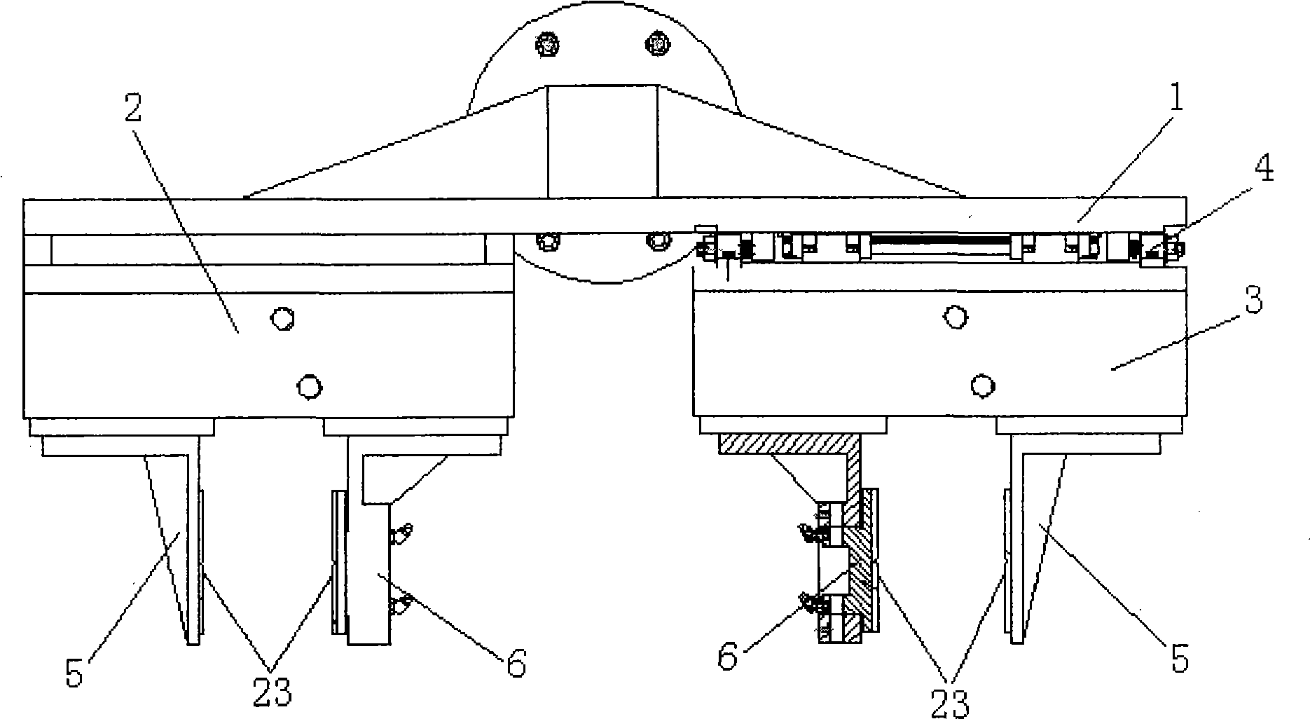
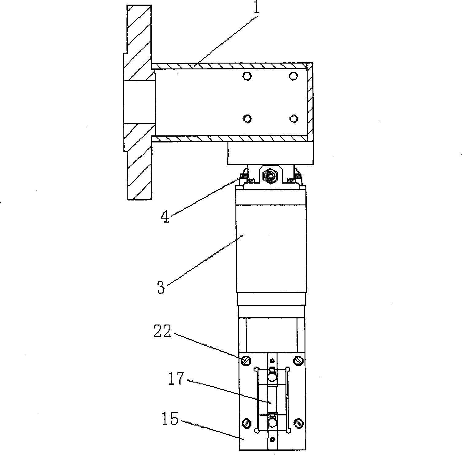
[0016] Such as figure 1 , figure 2 As shown, the present invention includes a mounting bracket 1, two sets of clamping devices 2 and 3 arranged symmetrically, wherein one set of clamping devices 2 is directly fixedly connected to the bottom side of the mounting bracket 1, and the other set of clamping devices 3 passes through a The cover floating mechanism 4 is connected to the other side of the bottom of the mounting bracket 1 . Simultaneously, the bottoms of the two clamping devices 2, 3 are respectively symmetrically provided with a jaw 5 and a floating jaw 6, and the jaw 5 and the floating jaw 6 are driven by an air control device in the prior art to move oppositely or relative to each other.

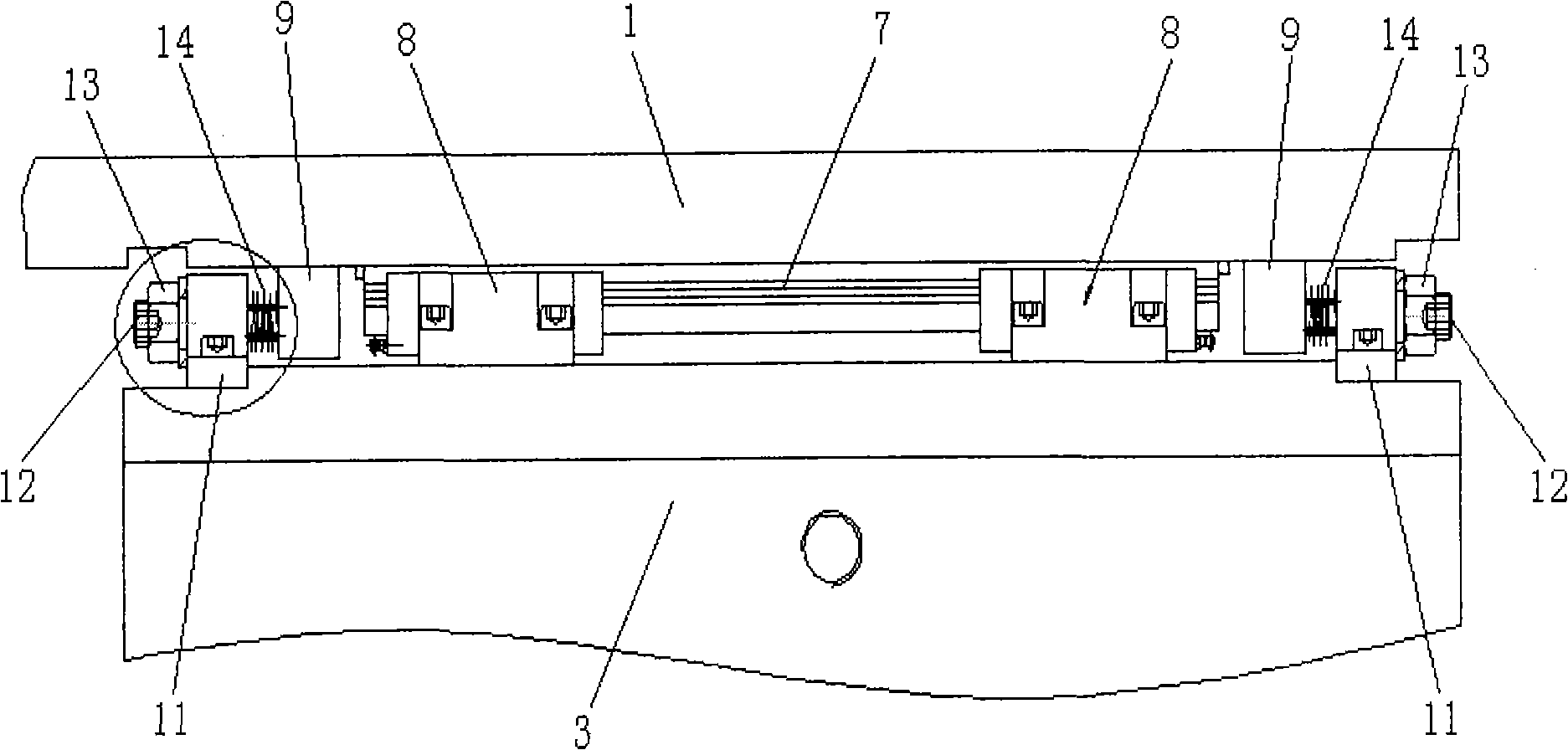
[0017] Such as image 3 , Figure 4 As shown, the floating mechanism 4 includes a guide rail 7 fixedly installed on the bottom of the mounting bracket...


PUM


Abstract

The invention relates to an automatic flexible fixture which is characterized in that the fixture comprises a mounting frame and two sets of holding devices which are symmetrically installed, wherein, one set of the holding device is directly and fixedly connected with one side of the bottom part of the mounting frame while the other set of the holding device is connected with the other side of the bottom part of the mounting frame by a set of floating mechanism; the bottom parts of the two sets of the holding devices are symmetrically provided with two clamping jaws respectively. The introduction of the floating mechanism avoids the excessive positioning of the two sets of the holding devices to the clamping work pieces in the process of clamping, which can not only compensate various positioning errors and guarantee stable grasping but also avoid the damage of work pieces caused by the reasons such as over-positioning etc.; the two sets of the holding devices are respectively provided with a floating clamping jaw, which can compensate the shape errors of the surfaces of the work pieces, increase the contact surface of the fixture and the work pieces and lessen the damage of the surfaces of the work pieces.

Description

technical field [0001] The invention relates to a jig, in particular to an automatic flexible jig. Background technique [0002] With the advancement of science and technology, the degree of automation in all walks of life is getting higher and higher. In the handling industry, in order to perform automatic operations well, it is necessary to design automatic fixtures. However, in some occasions, the requirements for fixtures are very high, such as the handling of sand cores in the foundry industry. If the design of the fixtures is not reasonable, it will be difficult to automatically grab or cause damage to the workpiece due to the shape and position error of the workpiece. Contents of the invention [0003] In view of the above problems, the object of the present invention is to provide an automatic flexible fixture with a floating function. [0004] In order to achieve the above object, the present invention adopts the following technical solutions: an automatic flexi...

Claims


Application Information

Patent Timeline
Patent Type & Authority Applications(China)
IPC IPC(8): B25J15/00B25J19/00
Inventor 刘晓鸣徐岩李天伟高润璋刘晏
Owner 天津智通信息系统集成有限公司
Learn More