Rapid response infrared detector and method for making same
A fast-response, infrared light technology, applied in the field of photodetectors, which can solve problems such as slow response time
- Summary
- Abstract
- Description
- Claims
- Application Information
AI Technical Summary
Problems solved by technology
Method used
Image

Examples
Embodiment 1
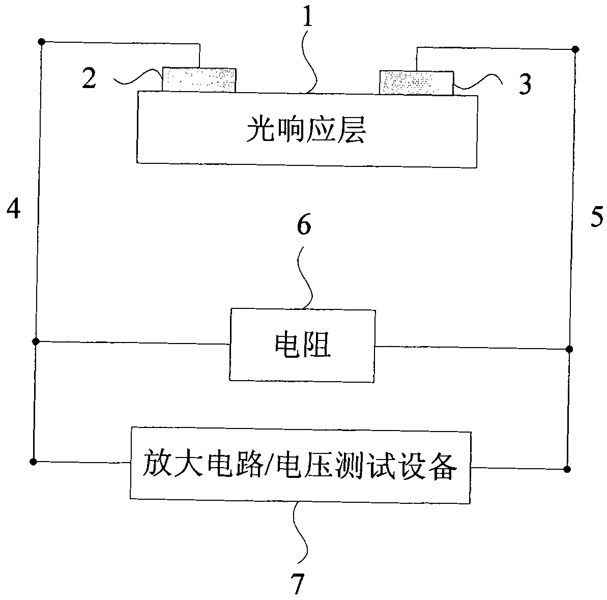
[0026] Please refer to figure 1 , Prepare one based on Al 2 O 3 Single crystal or Al 2 O 3 The preparation method of the film infrared light detector includes the following steps:
[0027] 1. First of all, the pulsed laser film forming process is adopted, and the aluminum alloy is 5mm×10mm×0.5mm. 2 O 3 Single crystal or Al 2 O 3 The film is divided into a silver film with a thickness of 1nm and an area of 5mm×1mm on both sides using a mask method;
[0028] 2. Take the samples made above and follow figure 1 The structure shown is made, the first electrode 2 and the second electrode 3 are vapor-deposited on 1, respectively, the first electrode lead 4 and the second electrode lead 5 are welded on the first electrode 2 and the second electrode 3, and the A resistor 6 of 1 MΩ is connected in parallel between the first electrode lead 4 and the second electrode lead 5, and the output ends of the two electrode leads can be connected to a voltage measuring device 7. This embodiment uses an...
Embodiment 2
[0031] Please refer to figure 1 , Prepare one based on Al 2 O 3 Single crystal or Al 2 O 3 The preparation method of the film infrared light detector includes the following steps:
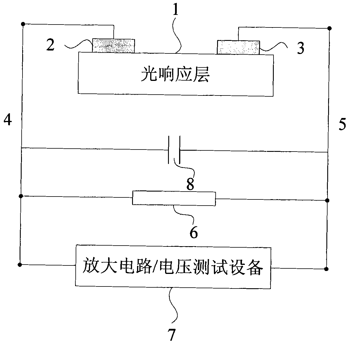
[0032] 1. First of all, using magnetron sputtering film production process, in 5mm × 10mm × 0.5mm Al 2 O 3 On the single crystal, an aluminum film with an area of 5mm×1mm and a thickness of 10μm is deposited on both sides by a mask method;
[0033] 2. Take the samples made above and follow figure 1 As shown in the structure, the first electrode lead 4 and the second electrode lead 5 are welded to the first electrode 2 and the second electrode 3 respectively, and 1MΩ is connected in parallel between the first electrode lead 4 and the second electrode lead 5 The resistance 6, the output ends of the two electrode leads can be connected to a voltage measuring device 7. This embodiment uses an amplifier circuit or an oscilloscope.
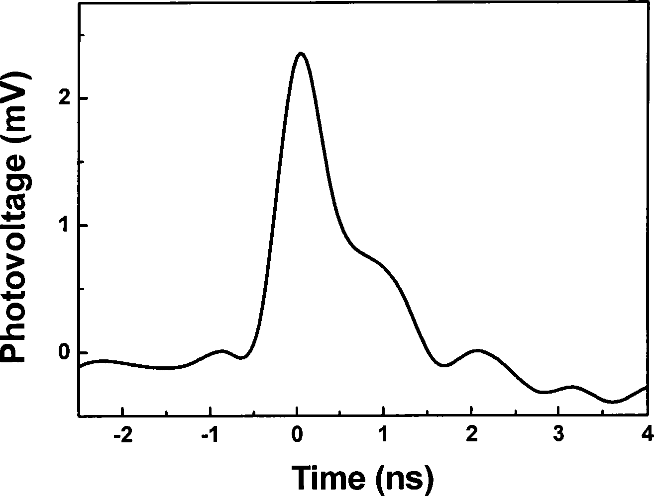
[0034] The prepared detector probe is irradiated by 808nm infrared laser, an...
Embodiment 3
[0036] Please refer to figure 1 , Prepare one based on Al 2 O 3 Single crystal or Al 2 O 3 The preparation method of the film infrared light detector includes the following steps:
[0037] Will Al 2 O 3 Single crystal or Al 2 O 3 The film is made like figure 1 The detector shown outputs a photovoltaic signal under the irradiation of a 980nm infrared laser.
[0038] 1. First of all, using a conventional spot welding machine, in the 5mm × 10mm thickness of 1nm Al 2 O 3 An indium electrode with an area of 1mm2 and a thickness of 1μm is welded on the film;
[0039] 2. Take the samples made above and follow figure 1 The structure shown is made, the first electrode lead 4 and the second electrode lead 5 are welded to the first electrode 2 and the second electrode 3 respectively, and 0.1Ω is connected in parallel between the first electrode lead 4 and the second electrode lead 5 The output ends of the two electrode leads can be connected to the voltage measuring device 7. In this embodime...
PUM
 Abstract
Description
Claims
Application Information