Ultrasonic electromotor using vertical vibration sandwich energy converter cylinder stator

A technology of ultrasonic motors and transducers, applied in the direction of piezoelectric effect/electrostrictive or magnetostrictive motors, generators/motors, electrical components, etc., can solve problems such as mechanical output capacity constraints, and achieve simplified structure, Effects of eliminating adverse effects and improving controllability

Inactive Publication Date: 2011-04-27
HARBIN INST OF TECH
View PDF0 Cites 0 Cited by
  • Summary
  • Abstract
  • Description
  • Claims
  • Application Information

AI Technical Summary

Problems solved by technology

[0003] In order to solve the problem that the mechanical output capability of the existing ultrasonic motor is restricted due to the excitation of the piezoelectric ceramic sheet pasted by the metal elastic body, the present invention provides a cylindrical stator using a longitudinal vibration sandwich transducer ultrasonic motor

Method used


Image

  • Ultrasonic electromotor using vertical vibration sandwich energy converter cylinder stator
  • Ultrasonic electromotor using vertical vibration sandwich energy converter cylinder stator
  • Ultrasonic electromotor using vertical vibration sandwich energy converter cylinder stator

Examples


specific Embodiment approach 1

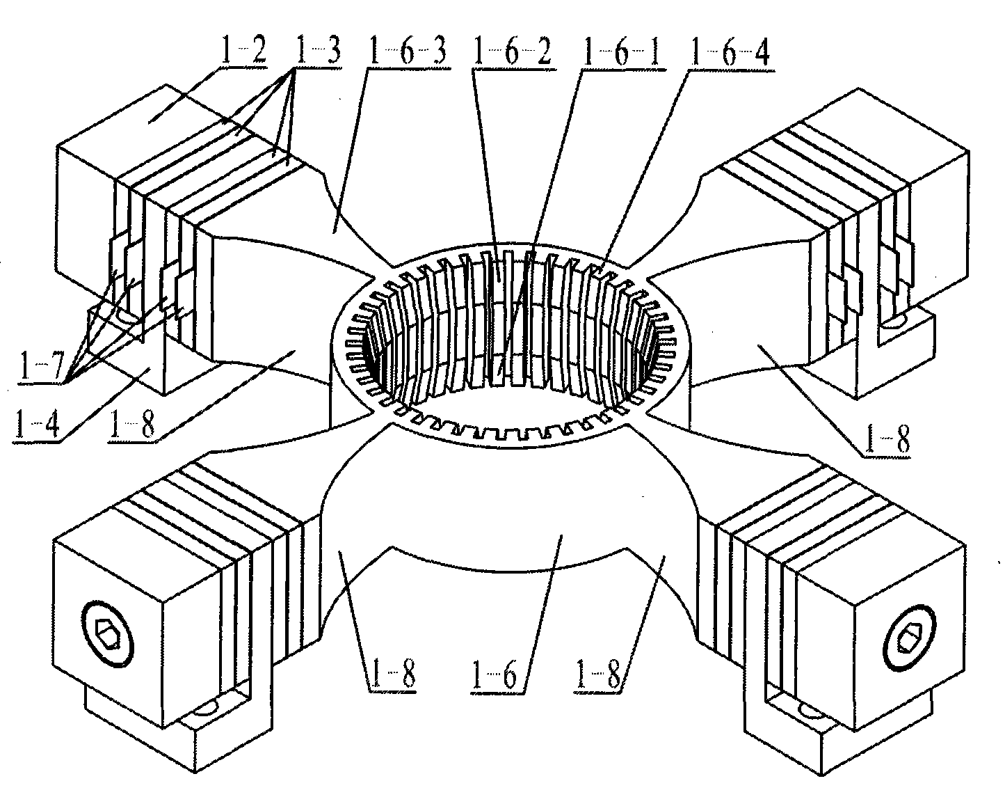
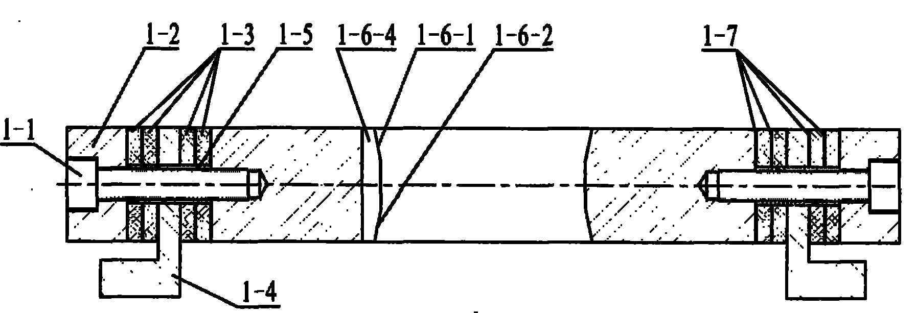
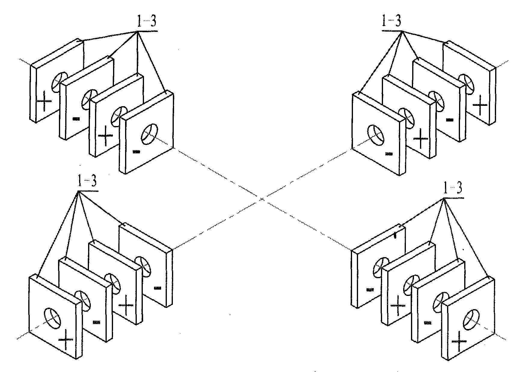
[0009] Specific Embodiment 1: The longitudinal vibration sandwich transducer type cylindrical stator of this embodiment is composed of a cylinder 1-6 and an even number of longitudinal vibration sandwich transducers 1-8; the even number of longitudinal vibration sandwich transducers 1 -8 is symmetrically fixed on the side wall of the cylinder 1-6, and each longitudinal vibration sandwich transducer 1-8 is composed of a horn 1-6-3, a rear end cover 1-2, and two pairs of piezoelectric ceramic sheets 1 -3, flange 1-4, thin copper electrode sheet 1-7 and insulating sleeve 1-5; the horn 1-6-3 is a quadrangular prism with a rectangular cross-section and tapering, and the horn 1- The small end face of 6-3 is fixedly connected with the outer surface of the cylinder 1-6; the section of the flange 1-4 is "L" shape, and the flange 1-4 is fixed on the horn 1- Between the big end of 6-3 and the rear end cover 1-2, the flange 1-4 is located at the nodal position of the longitudinal vibratio...

specific Embodiment approach 2

[0012] Embodiment 2: The difference between this embodiment and the longitudinal vibration sandwich transducer-type cylindrical stator described in Embodiment 1 is that the horn 1-6-3 and the cylinder 1-6 are made of a single piece The metal material is processed into a cylinder / horn integral piece.

[0013] In this embodiment, the horns 1-6-3 of the even number of longitudinal vibration sandwich transducers are processed into an integrated structure, which can reduce energy loss and help improve the controllability of the particle vibration track on the surface of the driving tooth. sex.

specific Embodiment approach 3

[0014]Embodiment 3: The difference between this embodiment and the longitudinal vibration sandwich transducer-type cylinder stator described in Embodiment 1 is that the inner surface of the cylinder 1-6 is processed with continuous comb-shaped driving teeth 1-6- 4. The upper and lower ends of the driving teeth 1-6-4 are respectively processed with an upper tapered surface 1-6-1 and a lower tapered surface 1-6-2.

[0015] The drive tooth 1-6-4 added in this embodiment is conducive to amplifying the amplitude of the particle vibration track on the surface of the stator. The upper end cone surface 1-6-1 and the lower end cone surface 1-6- 2. It is beneficial to increase the contact area between the stator and the rotor and increase the output torque.


PUM


Abstract

An ultrasonic motor adopting a longitudinal-vibration sandwiched transducer-typed cylindrical stator is provided, which relates to the technical field of ultrasonic motors and solves the problems that the mechanical output capability of the existing ultrasonic motor is restricted by a reason that a method that a metal elastomer is stuck to a piezoelectric ceramic slice is adopted for the excitation. Even numbers of longitudinal-vibration sandwiched transducers in the stator of the invention are symmetrically fixed on an outer side wall of a cylinder; an amplitude transformer of the sandwiched transducer is a quadrangular body with a rectangular section gradually narrows and a small end face of the amplitude transformer is fixedly connected with the cylinder; a flange is positioned at a nodal surface with longitudinal vibration of the transducer; two pairs of piezoelectric ceramic plates are respectively fixed between a back end face and the flange as well as between the flange and the amplitude transformer. A rotor with an axis and a rotor without an axis take the shape of a truncated cone and are embedded from the upward side and the downward side of the cylinder of the stator, wherein, a side face of the contact of the rotor and the cylinder is fixed with a wearable ring gasket and the stator is fixed on the base by the flange on the transducer. The invention can be applied to the field of the manufacturing of ultrasonic motors.

Description

technical field [0001] The invention relates to a longitudinal vibration sandwich transducer type cylindrical stator and an ultrasonic motor using the stator, belonging to the technical field of piezoelectric ultrasonic motors. Background technique [0002] Piezoelectric ultrasonic motor is a kind of piezoelectric ultrasonic motor that uses the inverse piezoelectric effect of piezoelectric ceramics to excite vibration in the ultrasonic frequency range in the elastic body, and forms a particle motion with a specific trajectory at a specific point or area on the surface of the elastic body, and then passes through the stator, The frictional coupling between the rotors converts the microscopic motion of the particle into the macroscopic motion of the rotor. It has the advantages of low speed and high torque, no need for a transmission mechanism, no electromagnetic interference, fast response, and self-locking when power is off. As a piezoelectric driver, it has Very wide range ...

Claims


Application Information

Patent Timeline
Patent Type & Authority Patents(China)
IPC IPC(8): H02N2/12H02N2/10
Inventor 刘军考刘英想陈维山谢涛石胜君
Owner HARBIN INST OF TECH
Why Eureka
Try Eureka