Ventilation device for a fuel container

A technology of exhaust device and fuel tank, which is applied in the direction of power device, layout and packaging combined with fuel supply of internal combustion engine, can solve problems such as interference and energy consumption of fuel pump, and achieves low control cost, simple control and low cost Effect

Inactive Publication Date: 2008-09-10
CONTINENTAL AUTOMOTIVE GMBH
View PDF0 Cites 6 Cited by
  • Summary
  • Abstract
  • Description
  • Claims
  • Application Information

AI Technical Summary

Problems solved by technology

However, the constant connection of the ejector pump to the fuel pump has the result that the ejector pump operates even with an empty liquid collector and fuel is unnecessarily conveyed through the ejector pump
This leads to disturbing foam formation in the fuel tank and unnecessary energy consumption of the fuel pump

Method used


Image

  • Ventilation device for a fuel container
  • Ventilation device for a fuel container
  • Ventilation device for a fuel container

Examples


Embodiment Construction

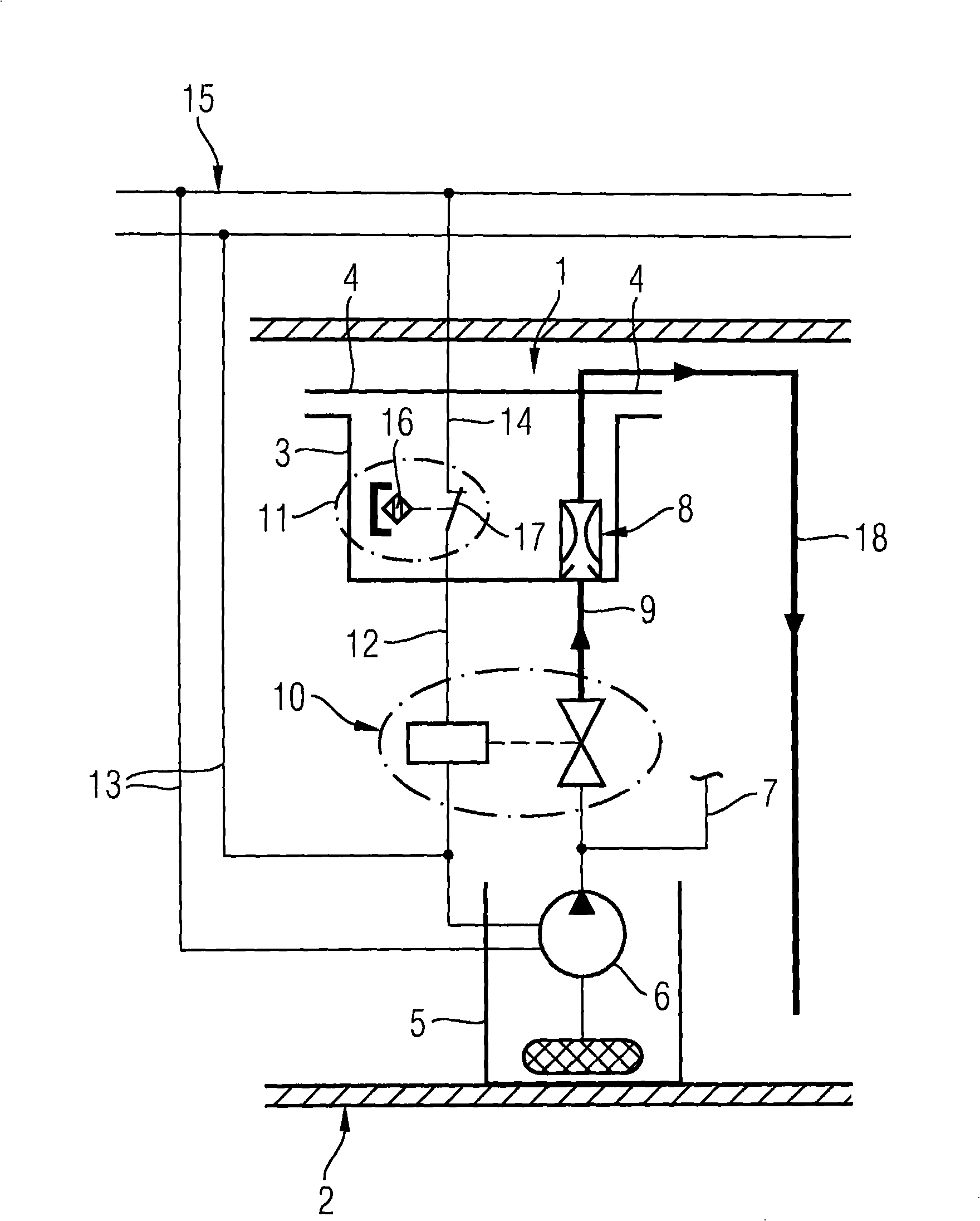
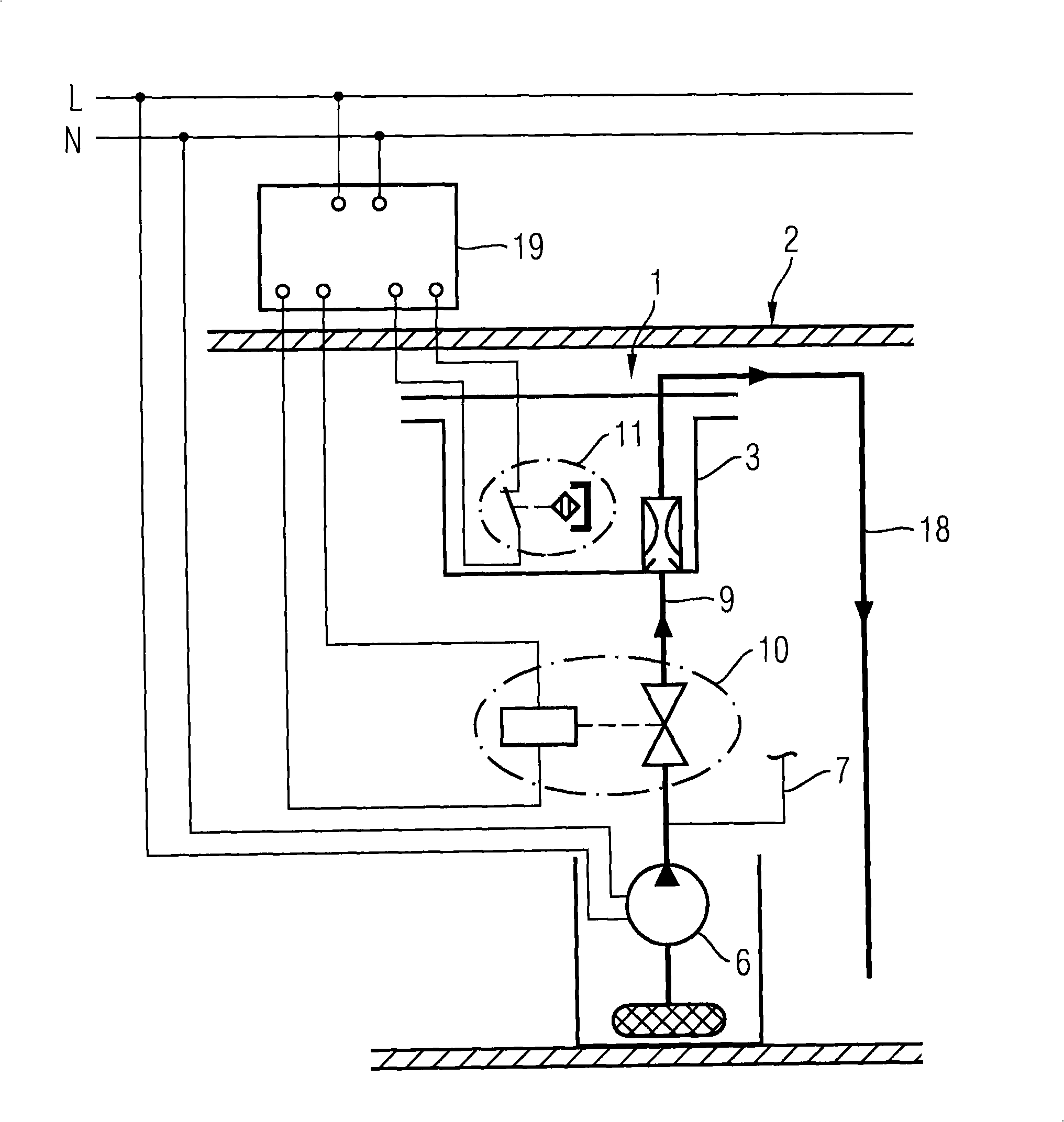
[0023] figure 1 An exhaust device 1 for a fuel tank 2 of a motor vehicle is shown, with a liquid trap 3 arranged in the upper region. The exhaust device 4 leads from the accumulator 3 to the side area of ​​the fuel tank 2. In addition, an anti-swirl box 5 with an electric fuel pump 6 is provided at the bottom of the fuel tank 2. The fuel pump 6 draws fuel from the anti-swirl box 5 and delivers the fuel to the internal combustion engine of a motor vehicle, not shown, through a supply line 7. A suction and injection pump 8 is provided in the liquid collector 3, and the suction and injection pump is connected to the supply pipe 7 of the fuel pump 6 through a delivery pipe 9. An electrically switchable valve 10 is provided in the conveying pipeline 9, and the valve is connected to a liquid level limit switch 11 provided in the liquid collector 3 through an electric wire 12. The liquid level limit switch 11, the electrically switchable valve 10, and the fuel pump 6 are also connected...


PUM


Abstract

A ventilation device (1) for a fuel container (2) with a liquid trap (3) and a suction jet pump (8) which is provided for emptying the liquid trap (3) has a filling-level limit switch (11) for detecting the filling level of fuel in the liquid trap (3). A valve (10) which is connected to the filling-level limit switch (11) is connected upstream of the suction jet pump (8). The suction jet pump (8) is first activated by means of the valve (10) when the intended filling level of fuel in the liquid trap (3) is exceeded.

Description

Technical field [0001] The invention relates to an exhaust device for a fuel tank, which has a liquid collector connected with at least one exhaust pipe and a suction pump arranged in the liquid collector, which is used to transport fuel from the liquid collector to In the fuel tank. Background technique [0002] Such exhaust devices are often used for exhausting fuel tanks during refueling and during operation and are therefore well known. In today's exhaust devices, in most cases, the exhaust pipeline leads from the de-bubble tank designed as a liquid collector to different sides of the fuel tank and perhaps through the activated carbon filter. The suction jet pump is connected with the fuel pump arranged in the fuel tank and sucks the fuel collected in the liquid collector and delivers the fuel back to the fuel tank. However, the continuous connection of the suction jet pump and the fuel pump results in that the suction jet pump runs even when the liquid collector is empty and...

Claims


Application Information

Patent Timeline
IPC IPC(8): B60K15/035
CPCB60K15/035B60K2015/03509
Inventor 克里斯蒂安·克罗格尔克努特·迈尔弗兰克·赖特尔
Owner CONTINENTAL AUTOMOTIVE GMBH
Why Eureka
Try Eureka