Tape cassette and tape printer

A tape printer and tape cassette technology, applied in the directions of ink ribbon cassettes, printing, ink ribbons, etc., can solve the problems of increased printing tape volume, increased operating costs, and larger blank space of printing tapes, so as to suppress the generation of waste. Effect

Inactive Publication Date: 2008-09-17
BROTHER KOGYO KK
View PDF3 Cites 82 Cited by
  • Summary
  • Abstract
  • Description
  • Claims
  • Application Information

AI Technical Summary

Problems solved by technology

Then, the front blank space of the printed tape produced (the blank area portion corresponding to the distance between the cutting position of the printed tape of the tape p

Method used


Image

  • Tape cassette and tape printer
  • Tape cassette and tape printer
  • Tape cassette and tape printer

Examples


no. 1 example

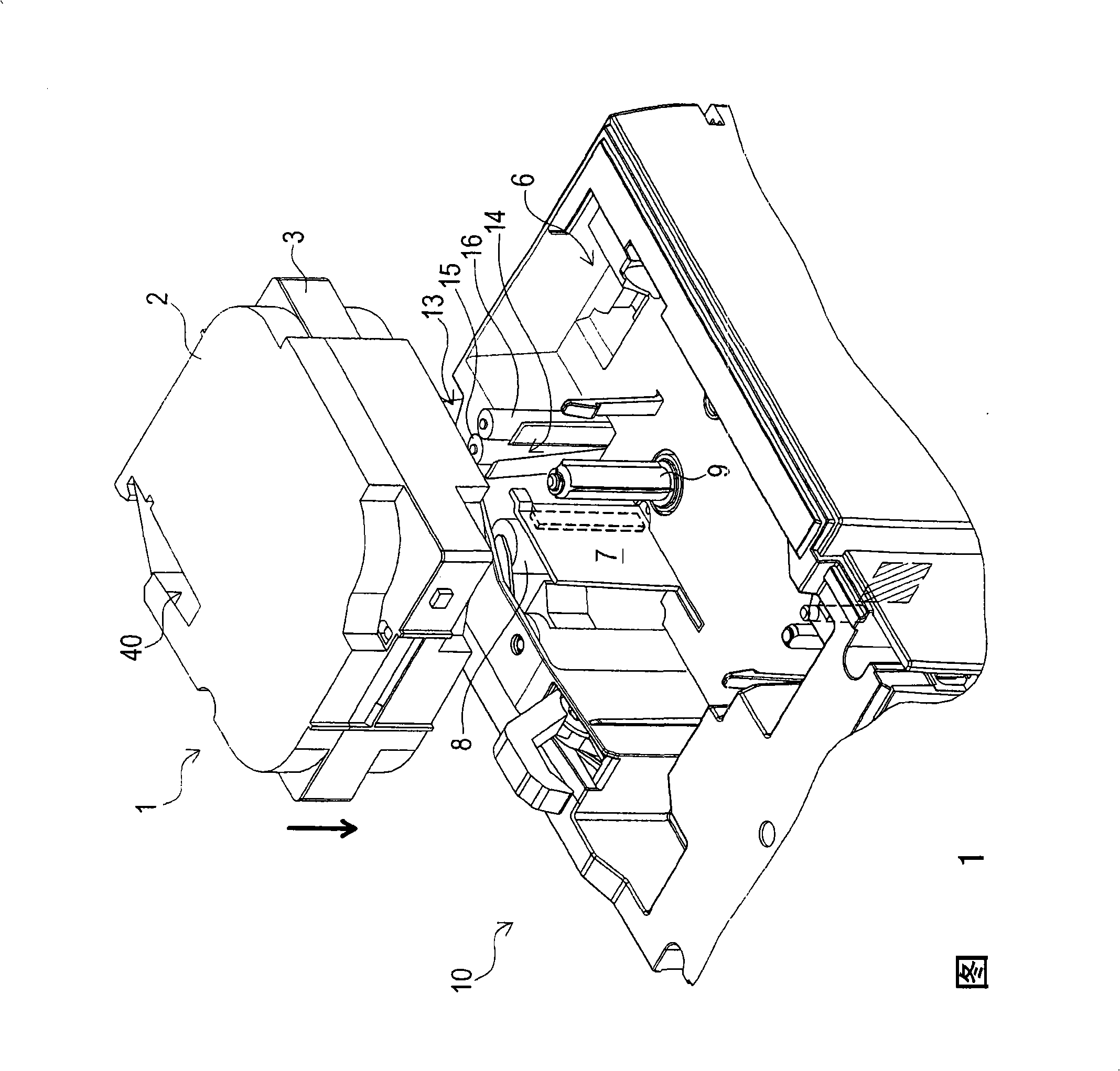
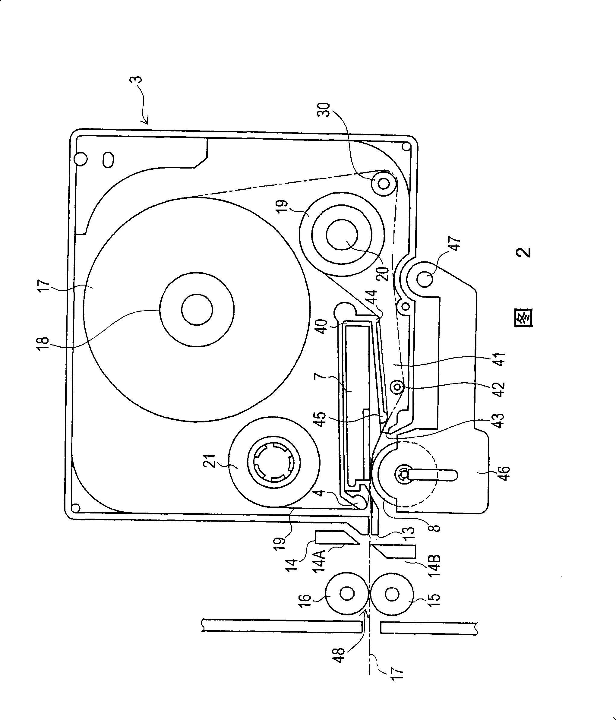
[0031] A description will now be given of a tape cassette and a tape printing apparatus according to a first embodiment based on FIGS. 1 and 2 .

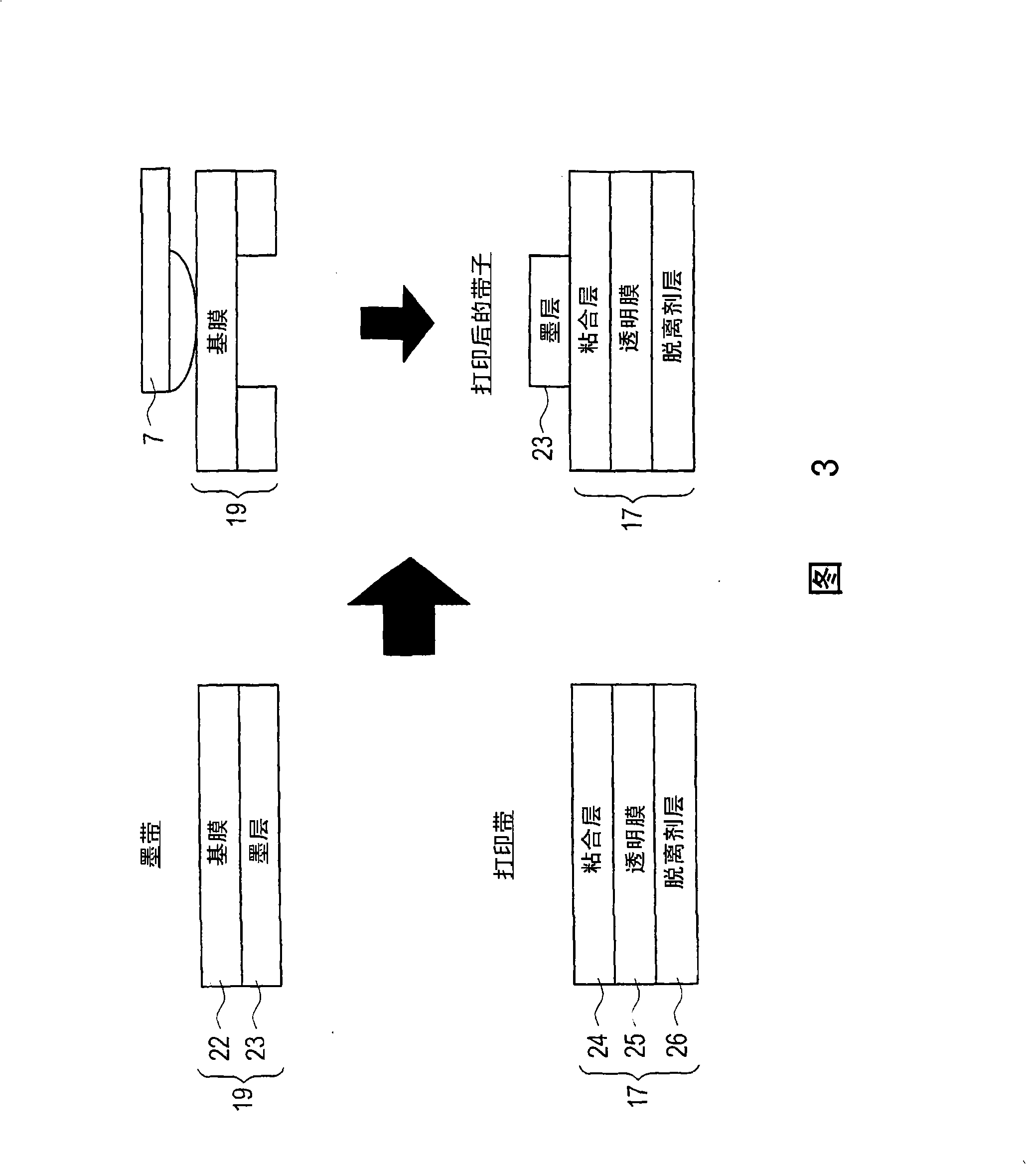
[0032] In FIG. 1 , a tape cassette 1 is detachable in a cassette accommodating portion 6 provided in a tape printing apparatus 10 . The tape cassette 1 has an upper case 2 and a lower case 3 . The upper case 2 serves as a cover covering the upper surface of the lower case 3 . A film tape reel 18 is arranged at a position slightly higher than the central part of the lower casing 3, and a film tape 17 is wound on the reel 18, as shown in FIG. 2 . The lower housing 3 also has an ink ribbon reel 20 and an ink ribbon take-up reel 21 arranged at the lower right position of the film reel 18, the ink ribbon 19 is wound on the ink ribbon reel 20, and the ink ribbon take-up reel 21 takes the The tape reel 20 pulls out the ink ribbon 19 and winds up the ink ribbon 19 consumed when printing characters.

[0033] The tape cassette 1 has a ther...

no. 2 example

[0059] Next, a tape cassette and a tape printing apparatus according to a second embodiment will be described based on FIGS. 5 and 6 .

[0060] The tape cassette and tape printing apparatus according to the second embodiment have the same basic configuration as the tape cassette 1 and tape printing apparatus 10 according to the first embodiment. Therefore, in the following description, the same components as those of the tape cassette 1 and the tape printing apparatus 10 according to the first embodiment are denoted by the same reference numerals, and the description will focus on the same components as those of the tape cassette 1 and the tape printing apparatus 10 according to the first embodiment. On different components of the device 10.

[0061] In FIG. 5 , a tape cassette 1 having an upper case 2 and a lower case 3 is detachable in a tape cassette accommodating portion 6 provided in a tape printing apparatus 10 . The upper case 2 serves as a cover covering the upper sur...


PUM

PropertyMeasurementUnit
Melting pointaaaaaaaaaa

Abstract

A tape cassette includes an ink ribbon provided with a base film coated with an ink layer thereon and a film tape provided with a transparent film with an adhesive layer formed on one surface thereof. When an adhesive layer of the film tape and the ink layer of the ink ribbon of the tape cassette into contact at a print position, the ink layer is adhered onto the adhesive layer on condition that the adhesive layer is heated to exhibit self-adhesive properties, and characters and the like are printed on the film tape. At a tape printing apparatus with the tape cassette mounted thereon, by arranging a cutter unit immediately downstream the thermal head, a post-printing tape is cut promptly after printing.

Description

[0001] Cross References to Related Applications [0002] This application is based on and claims priority from prior Japanese Patent Applications No. 2007-065712 filed on March 14, 2007 and No. 2007-065721 filed on March 14, 2007, all of which The content is incorporated herein by reference. technical field [0003] One or more aspects of the present invention relate to a tape cartridge including an ink ribbon having a base film on which an ink layer is formed, and a printing tape made of an ink ribbon having a pressure-sensitive adhesive layer formed on one surface thereof. It is made of a transparent film, and more particularly, relates to a tape cassette in which an adhesive layer of a printing tape and an ink layer of an ink ribbon are in contact at a printing position, and to a printer using the tape cassette. Background technique [0004] Various types of tape printing apparatuses have been conventionally proposed for manufacturing tapes on which characters are print...

Claims


Application Information

Patent Timeline
IPC IPC(8): B41J32/00B41J31/00B41J2/325
Inventor 山口晃志郎
Owner BROTHER KOGYO KK
Why Eureka
Try Eureka