Cavity resonancer with temperature stabilization and compensation function

A cavity-type, resonator technology, applied in the field of resonators, can solve problems such as changes in resonant frequency of resonators, and achieve the effect of temperature frequency compensation

Inactive Publication Date: 2008-09-17
GUANGZHOU EYECOM TELECOMM
View PDF0 Cites 13 Cited by
  • Summary
  • Abstract
  • Description
  • Claims
  • Application Information

AI Technical Summary

Problems solved by technology

[0006] Aiming at the shortcomings of the prior art, the object of the present invention is to provide a cavity resonator with a temperature stable

Method used


Image

  • Cavity resonancer with temperature stabilization and compensation function
  • Cavity resonancer with temperature stabilization and compensation function
  • Cavity resonancer with temperature stabilization and compensation function

Examples


Embodiment Construction

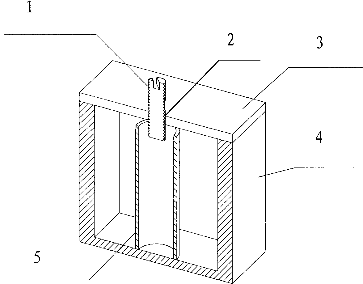
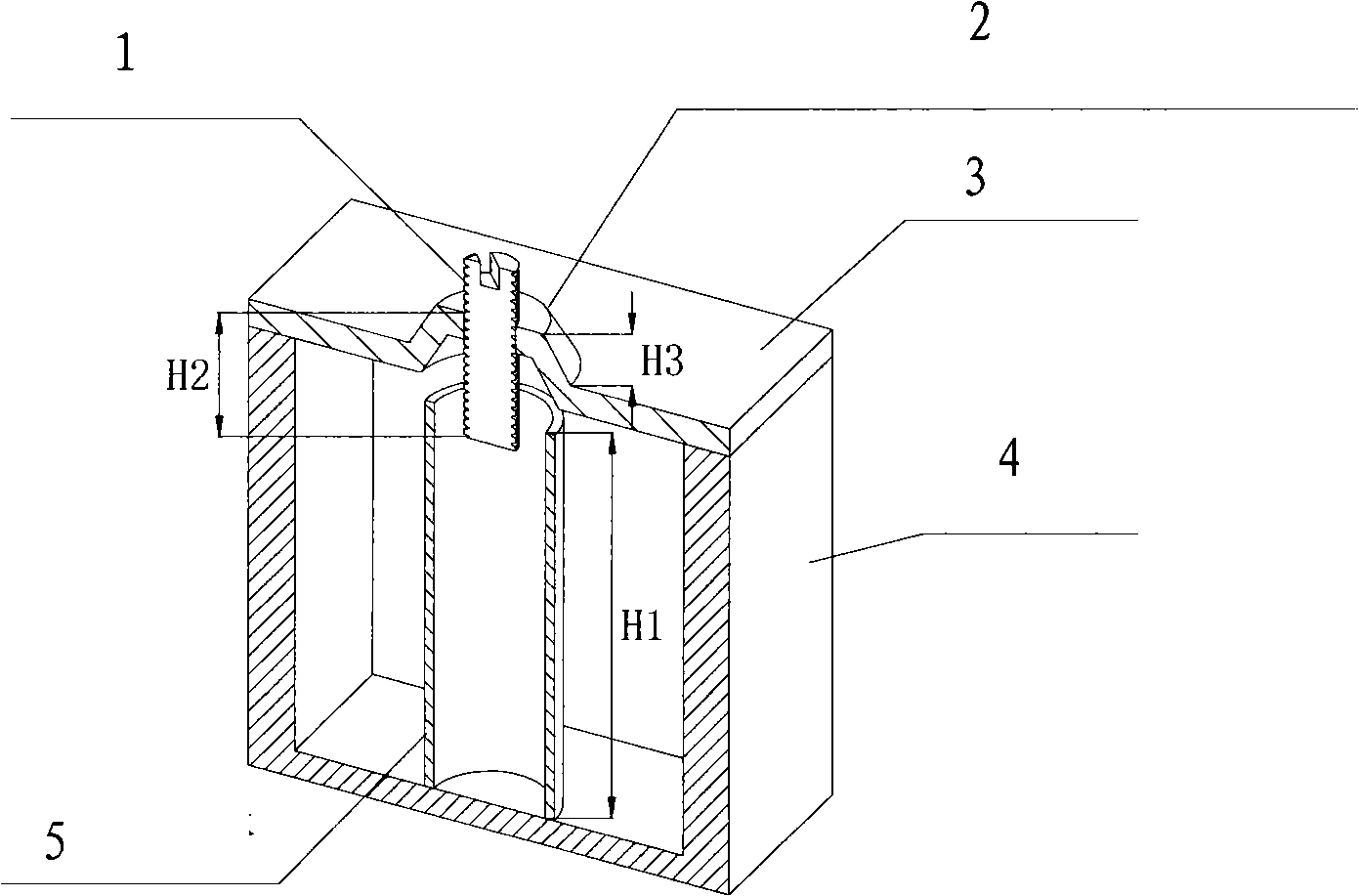
[0016] see image 3 , the cavity type resonator with temperature stable compensation function of the present invention includes a cavity 4 provided with an upper cover plate 3, an equivalent 1 / 4 (or its odd multiple) resonant frequency wavelength resonant rod 5 and an equivalent length tuning screw 1. Input and output electromagnetic coupling circuit (not shown in the figure), the upper cover plate 3 is provided with a tuning screw support structure 2, the resonant rod 5 is fixed in the resonant rod support structure in the cavity 4, and the tuning screw 1 is fixed on the tuning screw In the screw holes of the support structure 2, the materials of the resonant rod 5 and the tuning screw 1 are surface conductive materials with a low temperature expansion coefficient, and the materials of the upper cover plate 3, the tuning screw support structure 2 and the cavity 4 are surface conductive materials with a common expansion coefficient , The tuning screw support structure adopts a...


PUM


Abstract

The present invention discloses a cavity resonator which has temperature stable compensating function. The resonator comprises a cavity, a resonance rod and a tuning screw bolt. The cavity is provided with a tuning screw bolt supporting structure and a resonance rod supporting structure. The resonance rod is fixed in the resonance rod supporting structure. The tuning screw blot is fixed in the tuning screw blot supporting structure. The tuning screw bolt supporting structure or resonance rod supporting structure is a boss structure. The axial variation of the outward extension of the boss structure in the invention fundamentally compensates the gross mount of the axial variation of the inward extension of the tuning screw bolt and the resonator thereby that the equivalent physical length of the resonance rod is sustained to be relative constant and the stability of the frequency is guaranteed.

Description

technical field [0001] The invention relates to a resonator, in particular to a cavity type resonator with temperature stable compensation function. Background technique [0002] In the early days of telecommunication development, filters played an important role in circuits, and have made continuous progress with the development of communication technology. In 1910, the emergence of a novel multi-channel communication system, the carrier telephone system, triggered a complete technological revolution in the field of telecommunications and ushered in a new era of telecommunications. The new communication system requires the development of a new technology that can extract and detect signals in a specific frequency band, and the development of this technology has further accelerated the research and development of filter technology. [0003] In recent years, a large number of technical engineers have discovered an important problem in the process of developing filters, that ...

Claims


Application Information

Patent Timeline
IPC IPC(8): H03H9/08
Inventor 关淇凌元
Owner GUANGZHOU EYECOM TELECOMM
Why Eureka
Try Eureka