Diaphragm valve

A technology of diaphragm valve and spool, which is applied in the direction of lift valve, valve detail, valve device, etc., which can solve problems such as difficult to ensure and complex structure of the device, and achieve the effect of high responsiveness and increased volume

Inactive Publication Date: 2008-09-24
NIHON SPINDLE MFG CO LTD
View PDF1 Cites 10 Cited by
  • Summary
  • Abstract
  • Description
  • Claims
  • Application Information

AI Technical Summary

Problems solved by technology

[0017] However, since the diaphragm valve 50 can ensure a sufficient volume of the compressed air chamber 60a, it can sufficiently ensure the outflow of compressed air per unit time. The opening end of the cleaning air supply pipe 8 protruding from the pressure air chamber 60a of 60 becomes the valve seat 51, so it is difficult to ensure the accuracy of 0.02 to 0.05 mm generally required as the flatness of the end surface.
In addition, since the diaphragm valve 50 is premised to be used together with the sump 60, there is a problem that the structure of the device is complicated.

Method used


Image

  • Diaphragm valve
  • Diaphragm valve
  • Diaphragm valve

Examples


Embodiment 1

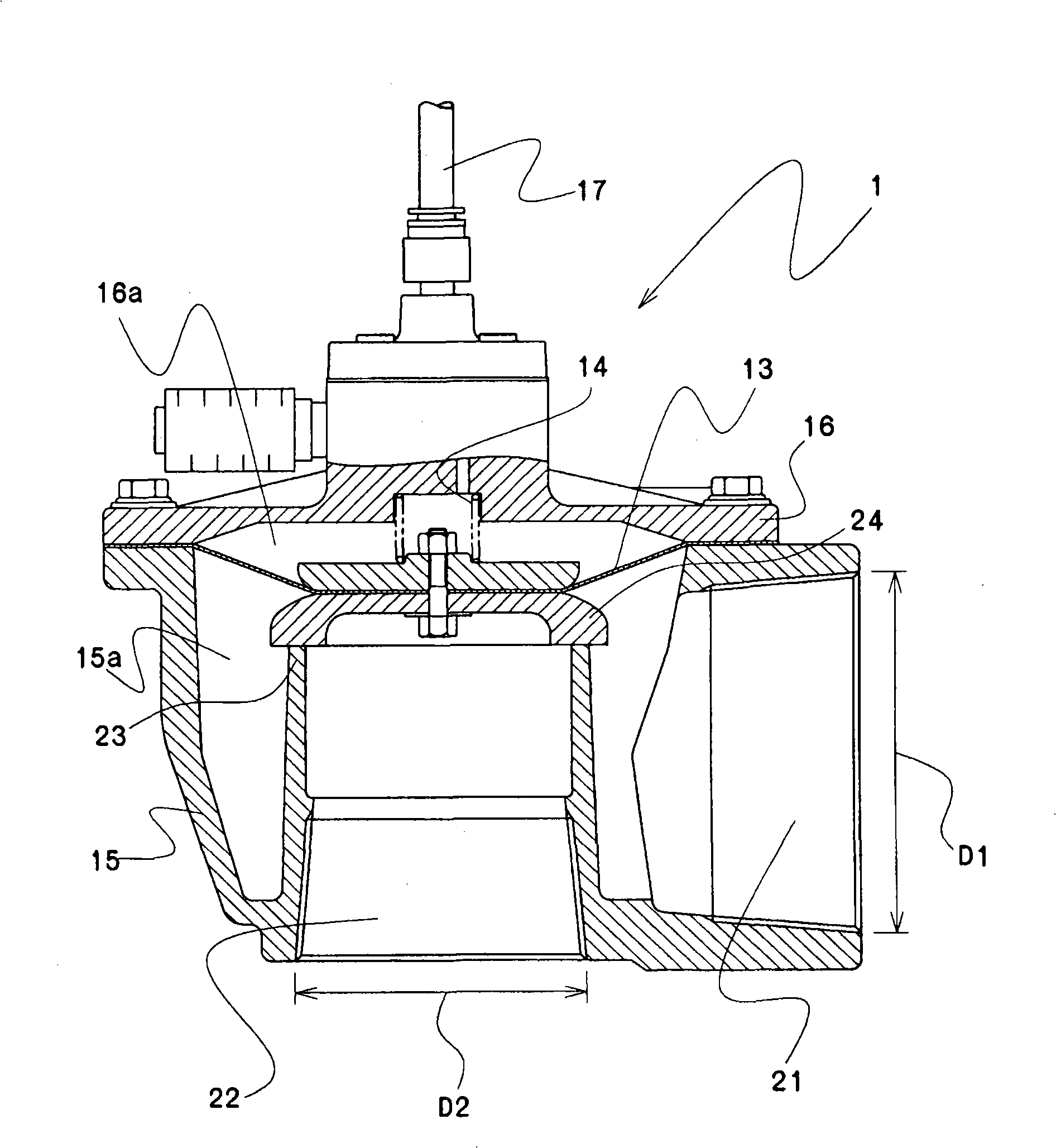
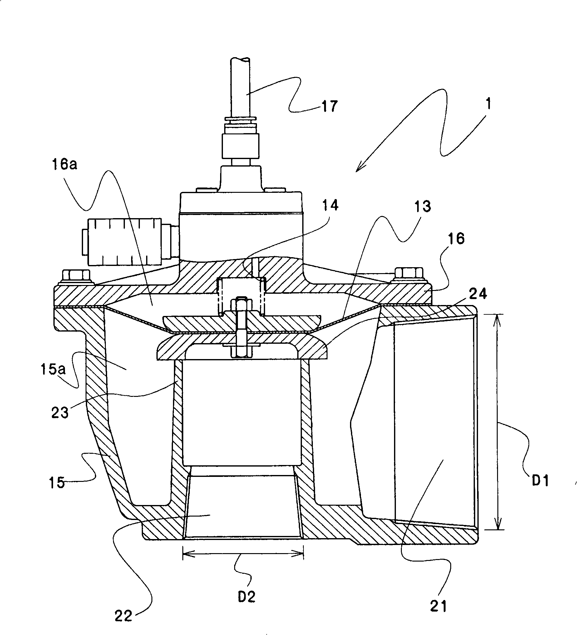
[0051] Figure 1 ~ Figure 2 An example of the diaphragm valve of the present invention is shown.

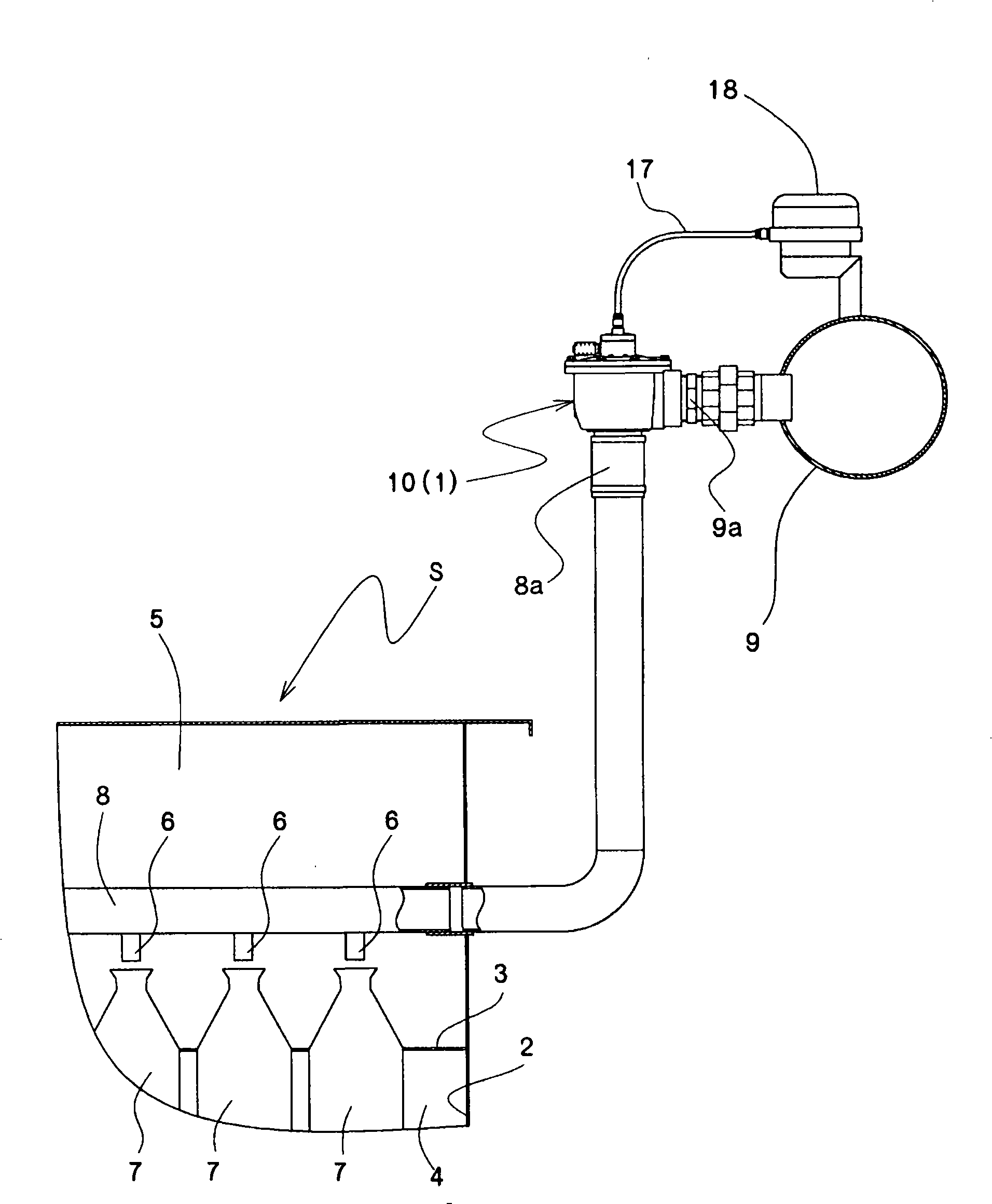
[0052] The diaphragm valve 1 is image 3 The diaphragm valve shown for the same bag type dust collector S as in the past is installed with the outer port 22 through the connecting pipe 8a provided at the opening end of the cleaning air supply pipe 8 of the bag type dust collector S, and the pressure air is supplied The pipe 9 and the connection pipe 9a are provided with an air inlet 21 through which the compressed air supply pipe 9 and the cleaning air supply pipe 8 are intermittently communicated.

[0053]The diaphragm valve 1 is composed of a main body 15, a cover member 16 having the inside as a valve chamber 16a, and a valve element 24 as in the conventional example. And the air inlet 21 connected with the pressure air supply pipe 9, and the outer port 22 with the inner end as the valve seat 23, and connected with the cleaning air supply pipe 8, the valve core 24 is arranged...


PUM


Abstract

This invention provides a so-called integral diaphragm valve with simple structure, which can function as a valve through mounting pipes in the front and the back, and is able to guarantee the outflow of the compressed air in unit time and improve the clean effect of the bag filter. In this invention, the diaphragm valve is composed of a main body (15), a cover component (16) using the internal as a valve chamber (16a) and a valve plug (24); the main body (15) includes an air inlet (21) using the external as a pressure air chamber (15a) and connected with the pressure air chamber (15a) and a supply pipe (9) of pressure air, an external opening (22) using the internal end part as a valve base (23) and connected with a supply pipe (8) of cleaning air; said valve plug (24) is oppositely configured with the valve base (23) depending on a membrane (13) mounted at the connecting part of the main body (15) and the cover component (16); the supply pipe (9) of pressure air is enable to be intermittently connected to the supply pipe (8) of cleaning air through the valve plug (24) so that the ventilating cross section of the air inlet (21) is formed to be larger than that of the external opening (22).

Description

technical field [0001] The present invention relates to a diaphragm valve, in particular to the improvement of the diaphragm valve used for supplying pressure air for backwashing of a bag filter of a bag type dust collector. Background technique [0002] In general, bag-type dust collectors are widely used to collect dust contained in exhaust gas discharged from incinerators, electric furnaces, and the like. [0003] In this way, when a large amount of dust adheres to the bag filter and the ventilation resistance (pressure loss) rises above a specified value, backwashing conditions are selected to blow off dust, and pressure air is sprayed to perform backwashing. [0004] More specifically, the bag dust collector S that cleans the bag filter by backwashing, such as image 3 As shown, by dividing the wall 3, the inside of the frame body 2 is divided up and down, the lower part is used as the dust-containing air introduction chamber 4, the upper part is used as the clean air c...

Claims


Application Information

Patent Timeline
Patent Type & Authority Applications(China)
IPC IPC(8): F16K1/36F16K31/126F16K27/00
Inventor 蚊野敏之
Owner NIHON SPINDLE MFG CO LTD
Why Eureka
Try Eureka