Device and method for removing burr

A burr removal and burr technology, which is applied in the field of burr devices, can solve problems such as uneven wear of brushes and unreliable deburr removal

Inactive Publication Date: 2008-10-01
KYB CORP
View PDF1 Cites 15 Cited by
  • Summary
  • Abstract
  • Description
  • Claims
  • Application Information

AI Technical Summary

Problems solved by technology

[0003] The deburring device described in JP2002-1870514A has the following problem: Since it is a structure in which a part of the side surface in the circumferential direction of the brush contacts and grinds, when continuously removing the burrs of the member to be ground that is periodically conveyed, Brushes produce uneven wear
[0004] In addition, since the direction of the abrasive force of the brush to grind the polished member (hereinafter referred to as "grinding direction") is always a constant direction, when the burrs of a plurality of polished members are formed in the same grinding direction as the brush, even with The brush grinds the workpiece to be ground, and it is difficult for the brush to come into contact with the burrs, and the burrs may not be removed reliably

Method used


Image

  • Device and method for removing burr
  • Device and method for removing burr
  • Device and method for removing burr

Examples


Embodiment Construction

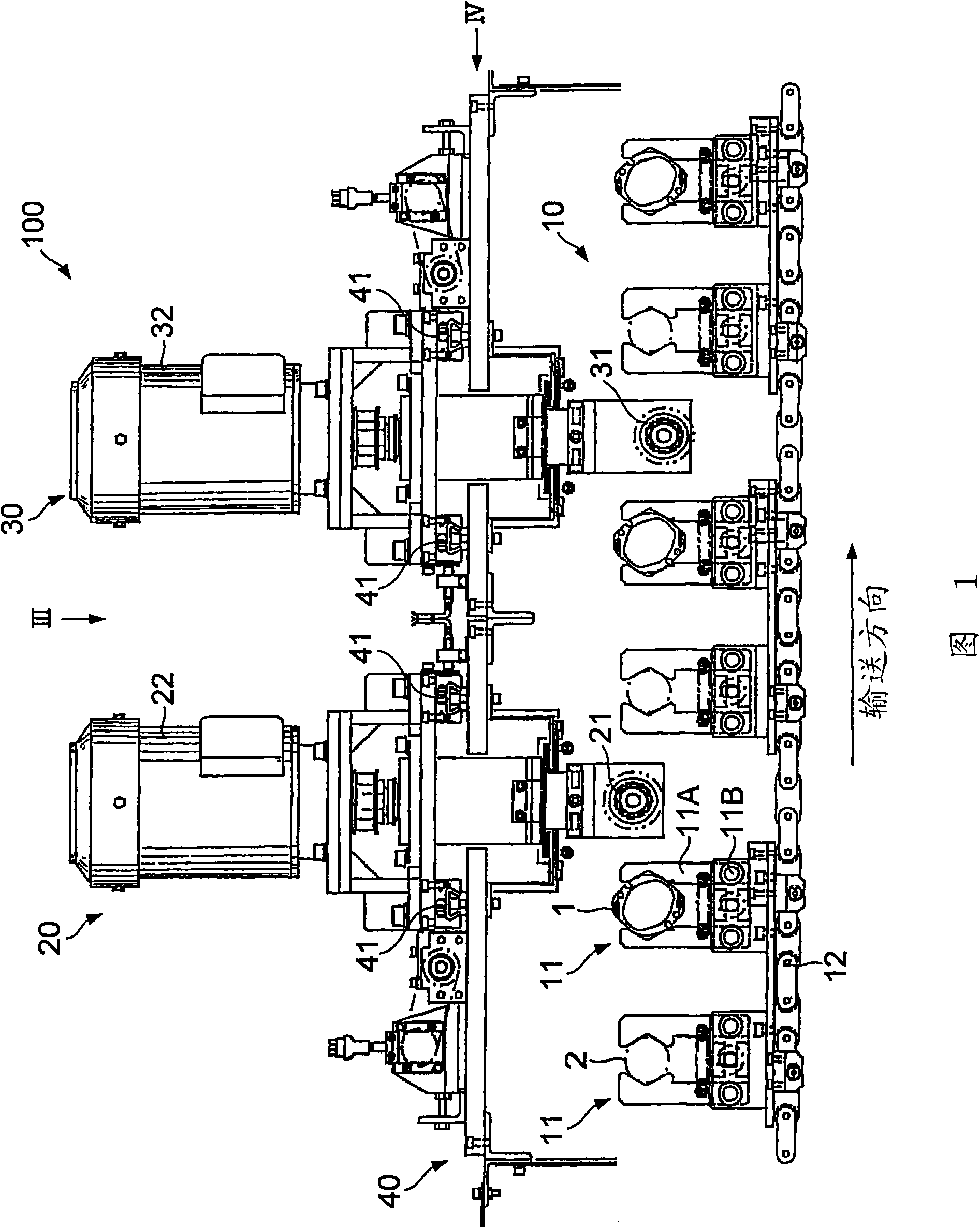
[0016] The structure of the deburring device 100 of the present invention will be described with reference to FIGS. 1 to 5 .

[0017] The deburring device 100 is a device for removing burrs formed on the end surfaces of the stator 1 and the rotor 2 of the vane pump.

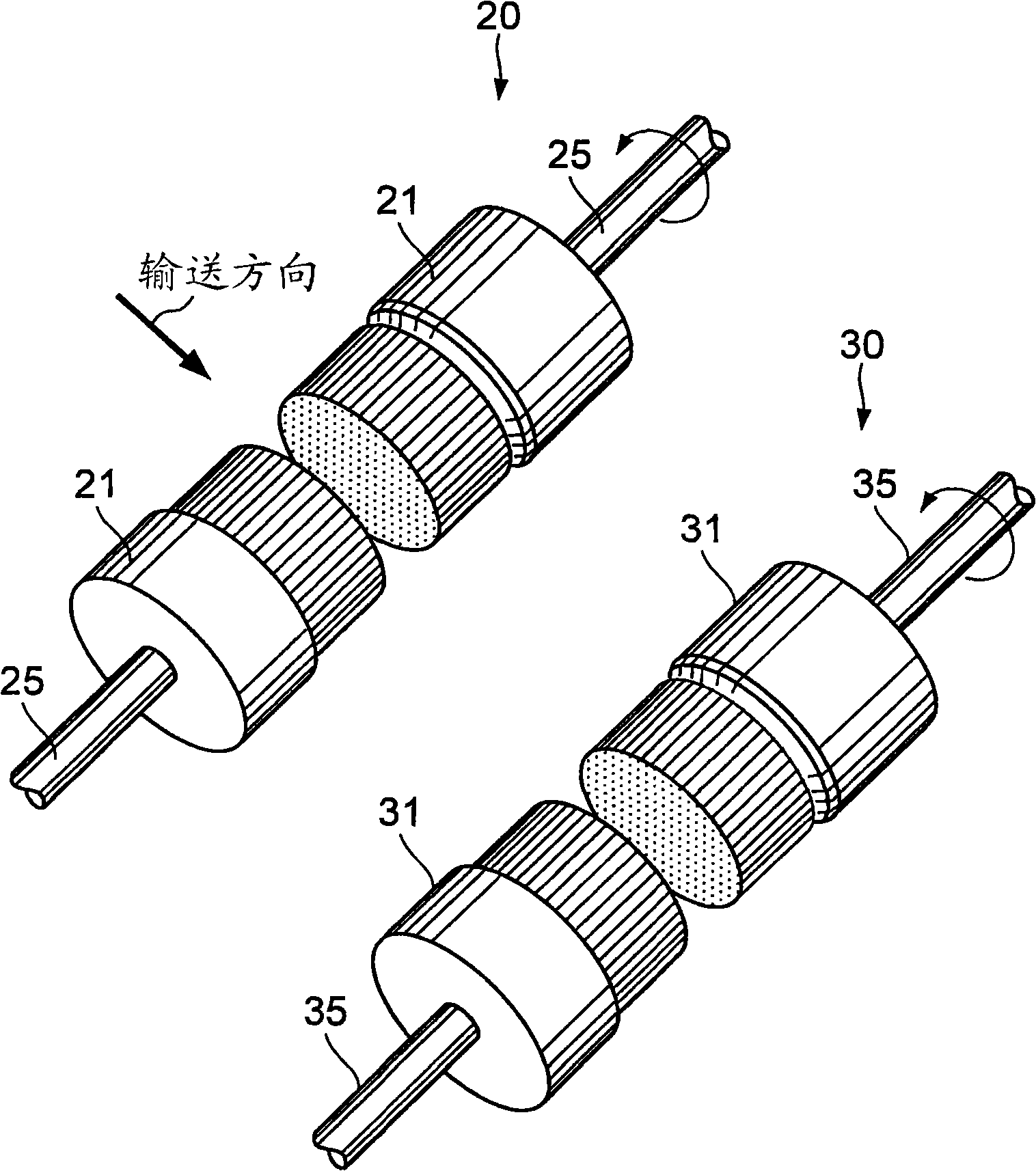
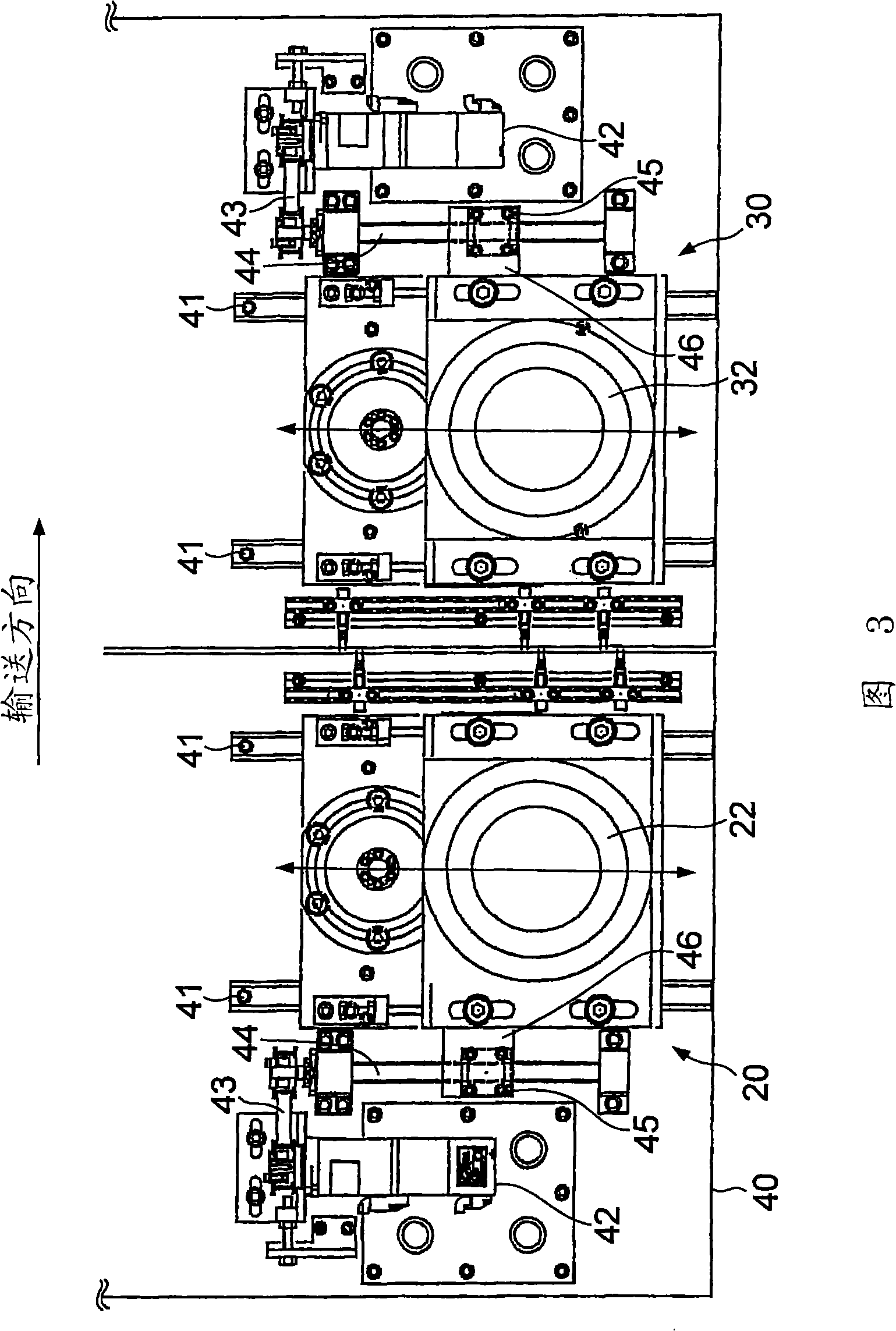
[0018] Referring to Fig. 1, the deburring device 100 has: a conveying part 10, which conveys the components to be ground such as the stator 1 and the rotor 2; . The deburring device 100 deburrs the stator 1 and the rotor 2 , but the deburring method for both is the same, and therefore, the member to be polished described below is the stator 1 .

[0019] The transport unit 10 is constituted by a holding unit 11 for holding the stator 1 and a conveyor belt 12 for moving the holding unit 11 .

[0020] The base portion 11B of the holding portion 11 has a pair of arms 11A. These arms 11A hold the stator 1 . The base portion 11B of the holding portion 11 is fixed to the conveyor belt 12 with bolts.

[0021] The co...


PUM


Abstract

The invention provides a burr removal device and a burr removal method. The burr removal device (100) comprises: grinding components (21, 31) which includes rotating shafts (25, 35) and grinding faces (21C, 31C) rotated along with and orthogonal to the rotating shafts (25, 35); a displacement component (10) which enables a grinded component (1) and the grinding components (21, 31) to relatively displace down a straight path; driving components (20, 30) which drive the grinding components (21, 31) to apply the grinding components (21, 31) to the grinded component (1) at a first grinding position that deviates from a central path of the grinded component (1), and to apply the grinding components (21, 31) to the grinded component (1) at a second grinding position that is isolated from the central path of the grinded component (1) and offset at one side opposite to the first grinding position.

Description

technical field [0001] The present invention relates to a device and method for removing burrs formed when processing metal components and synthetic resin components. Background technique [0002] JP2002-1870514A issued by the Japanese Patent Office in 2002 discloses a deburring device having a pair of brushes. This deburring device rotates a brush around a rotating shaft, and grinds a member to be polished, such as a connecting rod, with a side surface in the circumferential direction of the brush, thereby removing burrs. [0003] The deburring device described in JP2002-1870514A has the following problem: Since it is a structure in which a part of the side surface in the circumferential direction of the brush contacts and grinds, when continuously removing the burrs of the member to be ground that is periodically conveyed, Brushes experience uneven wear. [0004] In addition, since the direction of the abrasive force of the brush to grind the polished member (hereinafter...

Claims


Application Information

Patent Timeline
Patent Type & Authority Applications(China)
IPC IPC(8): B24B9/00B24B47/00
CPCB24B9/00B24B27/0076B24B29/005
Inventor 酒井明人
Owner KYB CORP
Why Eureka
Try Eureka