
Method and machine for rubberizing an annular surface of a body

A gluing machine and gluing technology, applied to tires, household utensils, and other household utensils, etc., can solve problems such as changes in stretching amount and uncontrolled third stretching

Inactive Publication Date: 2008-10-01
MARANGONI MECCANICA SPA
View PDF2 Cites 5 Cited by
  • Summary
  • Abstract
  • Description
  • Claims
  • Application Information

AI Technical Summary

Problems solved by technology

This allows very precise control over the total stretch that occurs between the extruder and the cot roll, however, there is no control over the third stretch, which is between the cot roll and the required stretch. There is always a gap between the glued surfaces and the amount of stretch usually varies

Method used


Image

  • Method and machine for rubberizing an annular surface of a body
  • Method and machine for rubberizing an annular surface of a body
  • Method and machine for rubberizing an annular surface of a body

Examples


Embodiment Construction

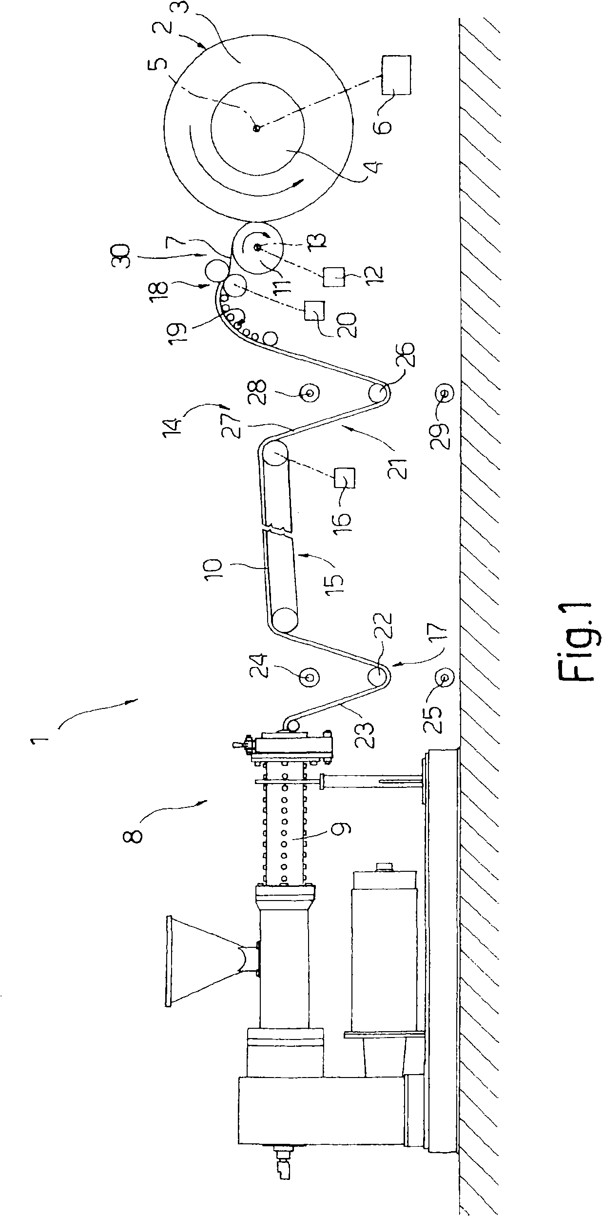
[0016] In FIG. 1, reference numeral 1 denotes the whole of a gluer for thermally gluing the annular surface of the carcass 2, in said related example, the toroid comprises a tire carcass 3 mounted on a mandrel 4, which is connected to The annular surface 2 is coaxial and rotates around the spindle axis 5 driven by the variable speed motor 6 .

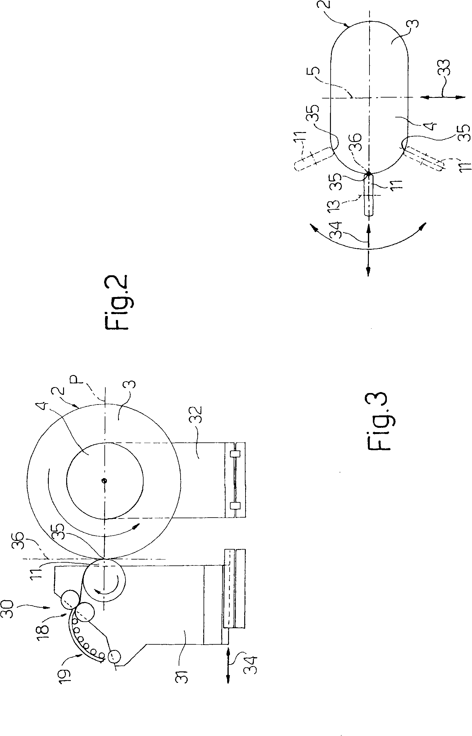
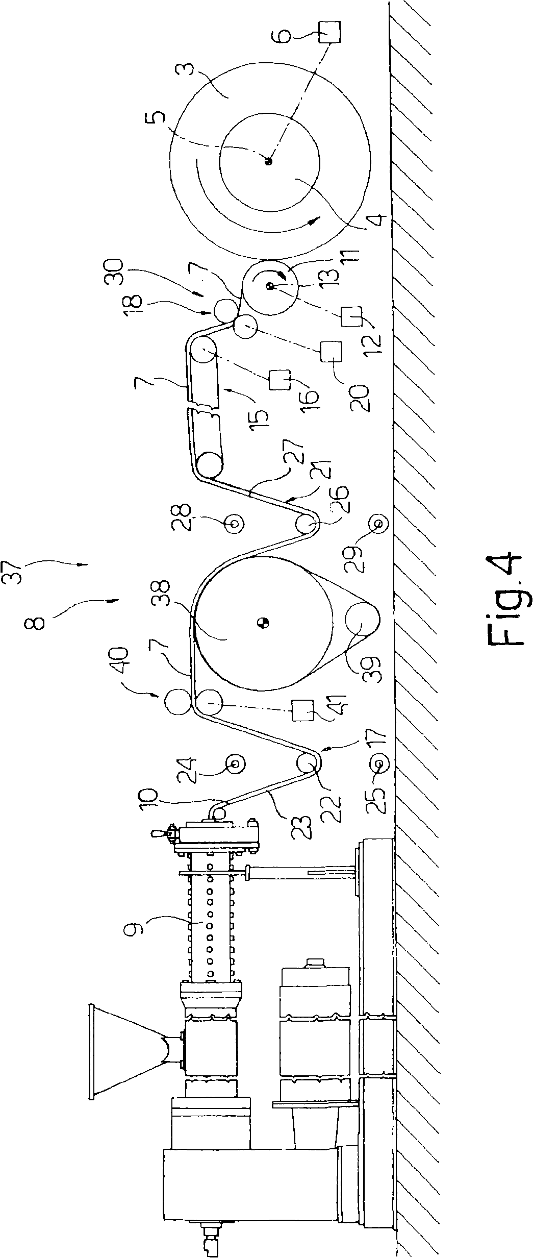
[0017] The annular surface 2 is continuously glued to itself by means of a strip 7 of elastic material having a predetermined cross-section, the elastic material being applied to the annular surface by means of a feeder 8 which is a glue applicator 1, comprising a screw extruder 9 for the production of elastomeric material, usually in the form of a circular cross-section strip 10, and a gumming roller 11 arranged in use to contact the annular surface 2 It is tangent to itself and rotates around an axis 13 parallel to the axis 5 driven by the transmission device 12 , and the axis 13 and the axis 5 form a plane P together.

[0018] The g...


PUM


Abstract

Method and machine for rubberizing an annular surface (2) of a body (3), the rubberized coating being applied by bringing said annular surface (2) into rotation about an axis (5) and progressively coating the annular surface (2) itself by means of a strip (7), of a determined section, of elastomeric material supplied by an extruder (9), shaped by at least one calender (18; 40) and applied, at a determined application speed, to the annular surface (2) to be rubberized by an a spreadingapplicator roller (11) presenting having a determined peripheral speed and positioned tangential to the annular surface (2) to be rubberized at a point (35) of application of the strip (7); the rotation of the annular surface (2) being controlled so as to maintain the constant application speed constant; and the section of the strip (7) being controlled by applying to the strip (7) itself a first, drawing stretch, always constant, between the spreading applicator roller (11) and the annular surface (2) to be rubberized, and a further drawing stretch upstream to the first drawingstretch; the further drawing stretch being constant to apply to the annular surface (2) a strip (7) with a constant section, or variable in order to apply to the annular surface (2) a strip (7) with variable section according to a determined law.

Description

technical field [0001] The present invention relates to a rubber coating on the annular surface of a carcass, preferably - but not necessarily - a tire carcass, with reference to which the invention will be described below in particular, without necessarily excluding general references. Background technique [0002] In the rubber industry, in order to apply glue to the annular surface of the tire carcass, it is known to use a glue applicator, in which the carcass to be glued is mounted on a mandrel, and the Driven by the motor, the mandrel rotates around its axis. The gluing process is as follows. Use an elastic material strip to gradually coat rubber on the annular surface to be gluing. The strip material has a definite cross-section. The machine applies glue to the annular surface to be glued. The feeder includes an extruder for pressing the elastic material into the form of a strip, usually of annular cross-section, and a coating machine tangential to the annular surface ...

Claims


Application Information

Patent Timeline
Patent Type & Authority Applications(China)
IPC IPC(8): B29D30/30B29D30/60
CPCB29D30/60B29D30/30B29D2030/4437B29D2030/4443B29D2030/445B29D2030/4456
Inventor 吉尔吉奥·马伦乔尼塞尔焦·法特
Owner MARANGONI MECCANICA SPA
Learn More