
Mold

A mold and medium channel technology, applied in the coating and other directions, can solve the problems of the increase of the process time, the deep drawing depth of the foil film, the limitation of the small angle structure, and the large equipment structure.

Inactive Publication Date: 2008-10-08
KANGZHUN ELECTRONICS TECH KUNSHAN +1
View PDF0 Cites 18 Cited by
  • Summary
  • Abstract
  • Description
  • Claims
  • Application Information

AI Technical Summary

Problems solved by technology

Therefore, the existing technology not only needs to design the heating device and the conveying device used in conjunction with it, resulting in a large structure of the entire equipment and high cost; it also leads to an increase in the entire process time and low efficiency
And this technology also has the limitation of foil film drawing depth and small angle structure.

Method used


Image

  • Mold
  • Mold
  • Mold

Examples


Embodiment Construction

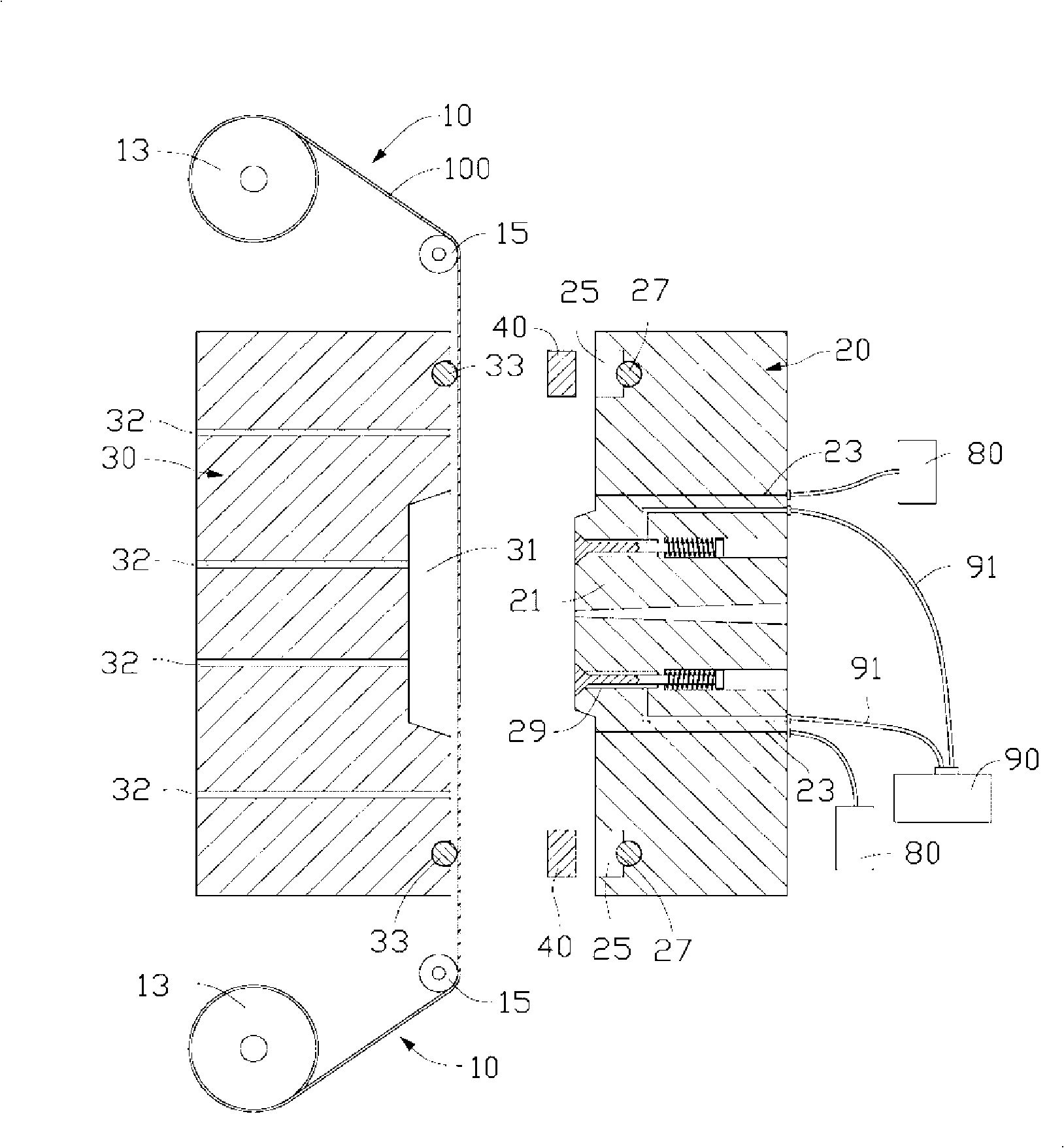
[0013] see figure 1 , an in-mold transfer printing device is used to transfer the pattern on the foil film 100 to the workpiece during injection molding, which includes a film feeding device 10, a male mold 20, a female mold 30, a pressing frame 40 and a heat medium Source 90.

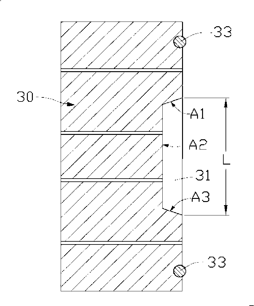
[0014] Please also refer to figure 2 , the master mold 30 offers a mold cavity 31, the mold cavity 31 includes a first surface A1, a second surface A2 and a third surface A3, the opening position of the mold cavity 31 is connected between the first surface A1 and the second surface A2 The length of the line is L, and the female mold 30 is provided with a plurality of exhaust grooves 32 in and around the mold cavity 31, and one end of the exhaust grooves 32 is connected with a vacuum device. A sealing ring 33 is provided between the periphery of the master mold 30 and the exhaust groove 32 .

[0015] read on figure 1 , the male mold 20 includes a matching portion 21 corresponding to the mold cavity...


PUM


Abstract

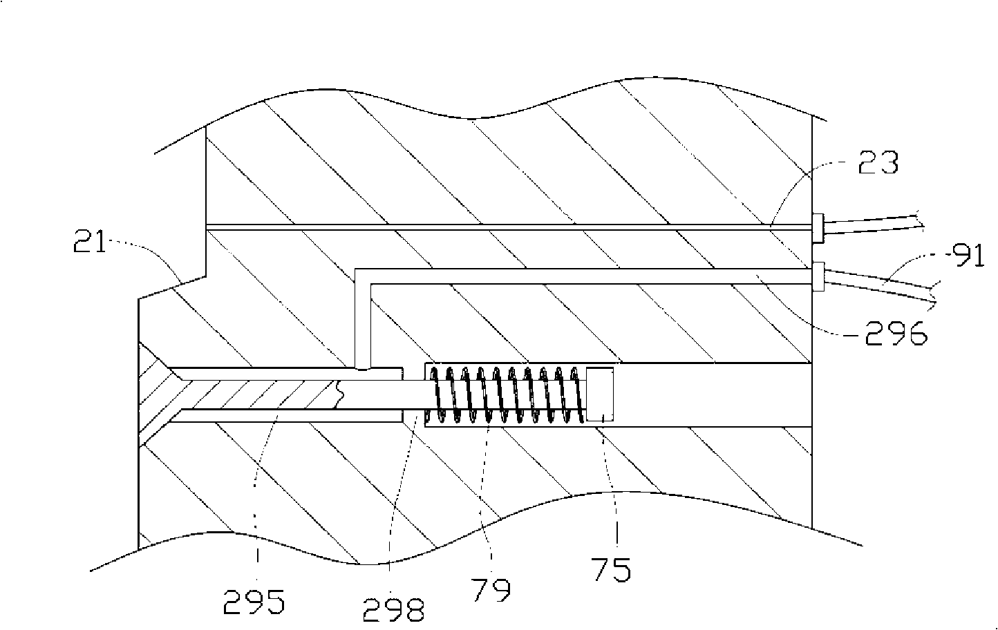
The invention relates to a die capable of applying the pressure to a foil film in advance in the transfer printing process inside the film, which comprises a medium channel arranged in the die; a medium source is communicated with the medium channel to feed medium into the medium channel so as to apply the pressure to the foil film. The die can apply the pressure to the foil film through the communication between the medium source and the medium channel so as to feed medium into the medium channel, thus greatly extending the stretching length of the foil film and achieving the effect of enabling the foil film to be perfectly attached to a die cavity even in a small angle.

Description

technical field [0001] The invention relates to a mold for in-mold transfer printing. Background technique [0002] In the in-mold forming process, the existing technology only relies on vacuuming on the mother mold side at room temperature to position the foil film in the cavity of the master mold. Therefore, the depth of foil film drawing is limited by the drawing of the foil film base layer itself at room temperature. For example, when the foil itself is stretched more than 20% of its natural state, it may be damaged or broken; moreover, when the mother mold cavity is designed with a small angle (especially at an acute angle) structure, due to vacuum Due to the size of the negative pressure generated and the normal temperature deformation of the foil base layer material, it is not easy for the foil to completely conform to the shape of the mold cavity. [0003] Based on the lack of the above existing technology, the industry has emerged a process for pre-heating the foil...

Claims


Application Information

Patent Timeline
Patent Type & Authority Applications(China)
IPC IPC(8): B29C33/12B29C33/10B29C33/00B29C45/26B29C45/34B29C45/14
CPCB29C45/1418B29C45/14827B29C2045/14213
Inventor 张浚元
Owner KANGZHUN ELECTRONICS TECH KUNSHAN
Learn More