
Straps with removable end connections

A technology of end connectors and connecting elements, which is applied in the direction of transmission belts, belt fasteners, belts/chains/gears, etc., can solve problems such as tension load limitations, and achieve the effect of improving strength and reducing structural burden

Active Publication Date: 2015-12-23
HABASIT AG
View PDF8 Cites 0 Cited by
  • Summary
  • Abstract
  • Description
  • Claims
  • Application Information

AI Technical Summary

Problems solved by technology

Here, there is the problem that the clamping device is arranged outside the neutral bending plane formed by the tension layer and is fastened to the tension layer by means of an additional fastening layer
A disadvantage of these straps and this type of connection is that, due to the helical wire element and its fastening to the end sections via the fabric layer, the permissible tensile load is severely limited, since otherwise the strap could be stretched, which in many applications is unacceptable, especially as the strap may stretch and slide

Method used


Image

  • Straps with removable end connections
  • Straps with removable end connections
  • Straps with removable end connections

Examples


Embodiment Construction

[0037] The following statement is true for the following description: If, in a figure, a reference number is shown for the sake of clarity of the drawing but is not mentioned in the directly relevant part of the description, then reference is made to the description before and after Part of the description is used to explain these reference numerals. Conversely, in order to avoid overcomplicating the figures, reference signs which are not relevant for immediate understanding are not shown in all figures. In this case, refer to the other drawings.

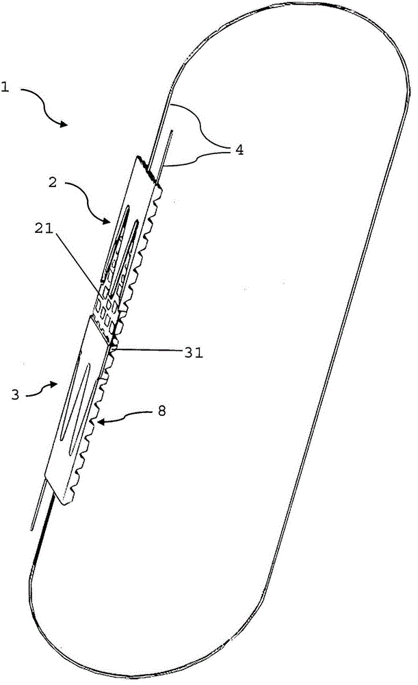
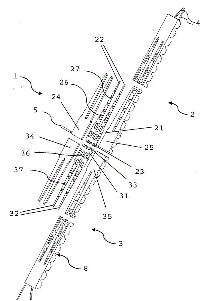
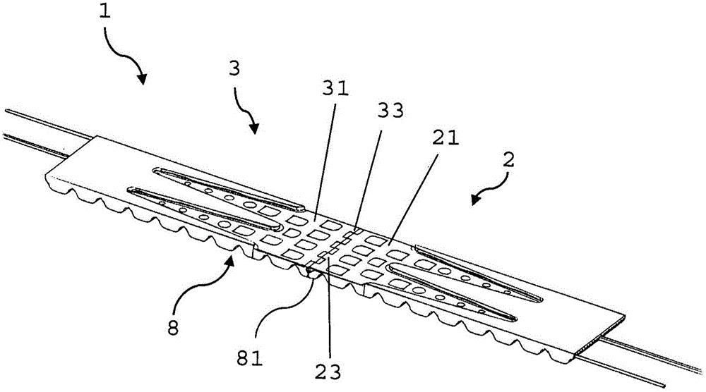
[0038] According to the invention the band 1's Figures 1 to 7 Exemplary embodiments shown in include (according tofigure 1 ) connects the first end portion 2 of the first connection element 21 and the second end portion 3 of the second connection element 31 . The two connecting elements 21 and 31 are here connected to each other via a hinge lever, as described in further detail below. In addition, the belt 1 has a tension layer ...


PUM

PropertyMeasurementUnit
elastic modulusaaaaaaaaaa

Abstract

The invention provides a belt (1) comprising a tension layer (4), a first end portion (2) at a first longitudinal end, a second end portion (3) at a second longitudinal end and a End connectors for joining the two end sections (2, 3). Here, the end connection comprises a first connection element (21) fastened to the first end part (2) and a second connection element (31) fastened to the second end part (3), wherein the first A connection element (21) and a second end connection piece (31) are detachably connected to each other and are made of stretch-resistant material. Each of the first connection element (21) and the second connection element (31) is integrally formed and together with the tension layer (4) forms a single neutral bending plane.

Description

technical field [0001] The present invention relates to straps having detachable end connectors for connecting end portions of the strap. Background technique [0002] Typically, this type of belt is a conveyor, drive or timing belt. Also sometimes referred to as a ribbon, this term is used hereinafter for purposes of clarity equally. These strips are flexible and can have different cross-sections, that is to say they can be wedge-shaped or flat, for example. The application is multifaceted, where in particular the transmission of forces and the transport of the material to be transported are the focus. In addition, timing belts can also be used, using the timing belt to control the periodic sequence or spatial position of the device. Sometimes the strips are not manufactured endless, but have end portions at their two longitudinal ends, which are then directly or indirectly connected to each other. [0003] A detachable end connection for a toothed belt is known from US...

Claims


Application Information

Patent Timeline
Patent Type & Authority Patents(China)
IPC IPC(8): F16G1/16F16G1/28F16G3/02B32B1/00
CPCF16G1/16F16G1/28F16G3/02B29C65/562B29C65/564B29C66/304B29C66/4322B29C66/4324B29C66/5241B29C66/73921B29C65/02F16G3/00
Inventor 托马斯·里克特海科·兰
Owner HABASIT AG
Learn More