Long bone fracture repositioning device
A reducer and long bone technology, applied in the field of fracture reducers, can solve the problems of difficult to achieve fracture reduction and fixation, inconvenient operation, etc., and achieve the effect of strengthening the awareness of minimally invasive, avoiding re-injury, and reducing trauma
- Summary
- Abstract
- Description
- Claims
- Application Information
AI Technical Summary
Problems solved by technology
Method used
Image
Examples
Embodiment 1
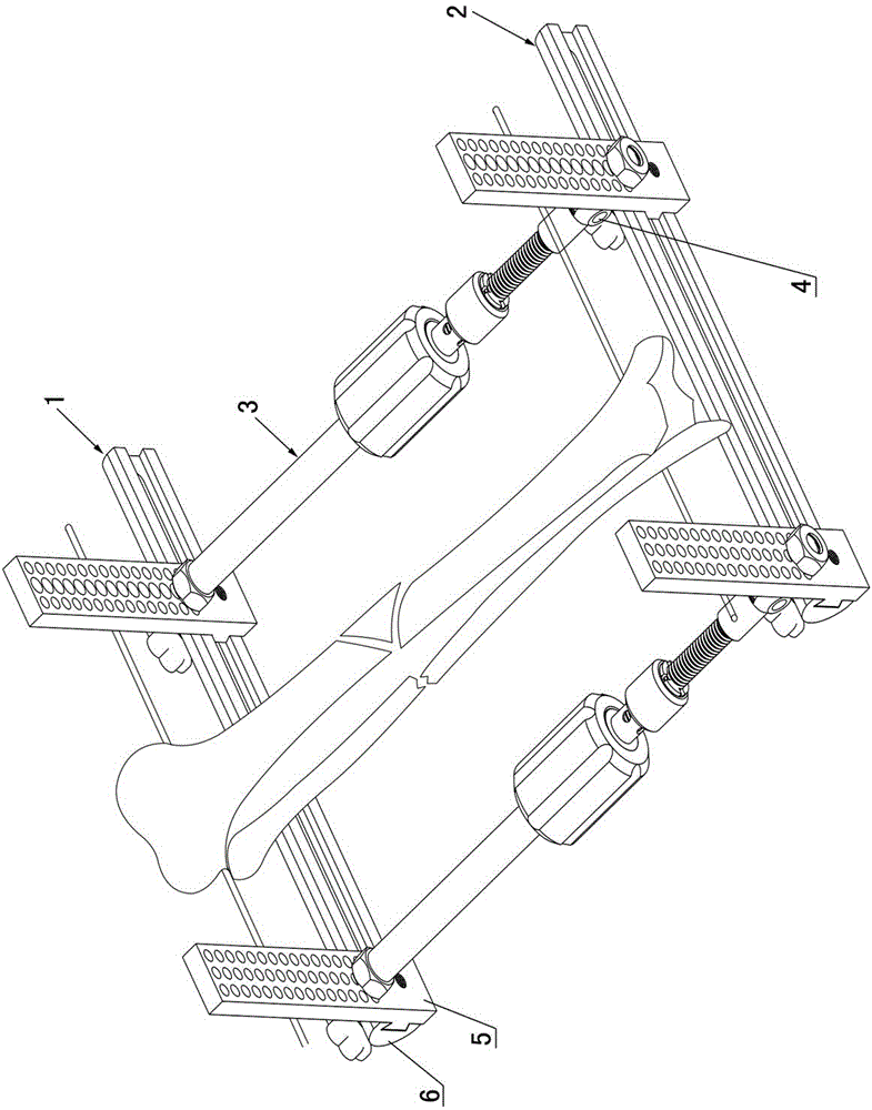
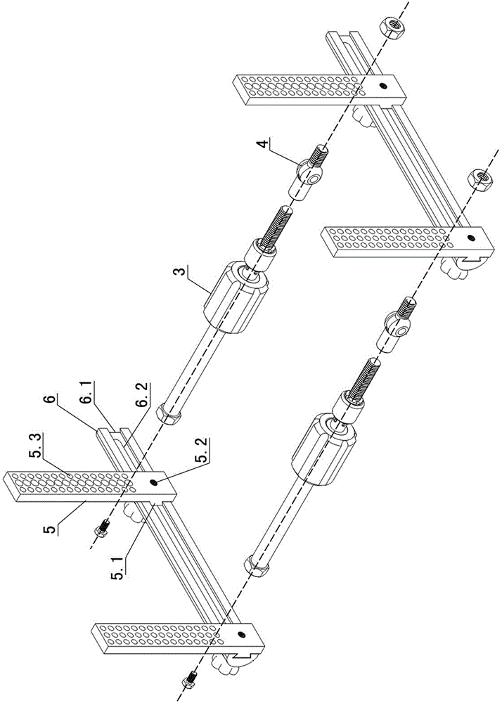
[0052] Embodiment one sees Figure 1-3 As shown, this long bone fracture reducer includes a proximal support 1, a distal support 2, a fast stretch extension rod 3 connected between the proximal support 1 and the distal support 2, and a proximal support 1 and a distal support. The steel needle fixing clip on the end support 2, and the steel needle clamped in the steel needle fixing clip.
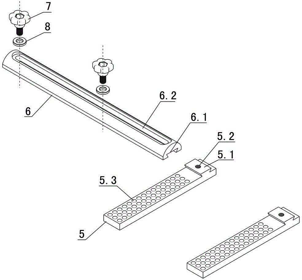
[0053] The proximal bracket 1 and the distal bracket 2 have the same structure, and both include a transverse groove-type reset slide plate 6 and two fixed sliding hole plates 5 connected to the groove-type reset slide plate 6 .
[0054] The proximal bracket 1 is also called a proximal U-shaped bow, and the distal bracket 1 is also called a distal U-shaped bow.
[0055] One side of the trough reset slide plate 6 is provided with a transverse guide chute 6.1, and a transverse guide slot 6.2 is provided between the bottom of the guide chute 6.1 and the other side of the trough reset slide plat...
Embodiment 2
[0067]Embodiment two see Figure 11-13 , the second embodiment is especially suitable for the reduction of femoral fractures. The difference from the first embodiment is that one or two tubular connecting rods 10 are also connected to the fixed sliding hole plate on the proximal support 1, and the tubular connecting rods 10 Also connected with the steel needle fixing clip on the top, the steel needle clamped in the steel needle fixing clip connected to the tubular connecting rod 10 is a threaded half needle.
[0068] The tubular connecting rod 10 is connected to the fixed sliding hole plate through the tubular rod connecting piece 9 . The tubular rod connector 9 includes a lower clamp 9.1 of the tubular rod connector and an upper clamp 9.2 of the tubular rod connector, and a tubular connecting rod groove 9.3 is provided between the lower clamp 9.1 of the tubular rod connector and the upper clamp 9.2 of the tubular rod connector. The lower clamp 9.1 of the tubular rod connecto...
PUM
 Abstract
Description
Claims
Application Information
 - R&D
- Intellectual Property
- Life Sciences
- Materials
- Tech Scout
- Unparalleled Data Quality
- Higher Quality Content
- 60% Fewer Hallucinations
Browse by: Latest US Patents, China's latest patents, Technical Efficacy Thesaurus, Application Domain, Technology Topic, Popular Technical Reports.
© 2025 PatSnap. All rights reserved.Legal|Privacy policy|Modern Slavery Act Transparency Statement|Sitemap|About US| Contact US: help@patsnap.com


