High-power LED road lamp

A technology for LED street lamps and LED lamp beads, which is applied in circuit layout, cooling/heating devices of lighting devices, outdoor lighting, etc., can solve the problems of high cost, inconvenient installation, complex structure, etc., and achieve high efficiency, sufficient reflection, and expansion Effects of lighting areas

Inactive Publication Date: 2008-10-08
黄爱国
View PDF1 Cites 15 Cited by
  • Summary
  • Abstract
  • Description
  • Claims
  • Application Information

AI Technical Summary

Problems solved by technology

[0003] The disadvantages of the above-mentioned prior art are: the use of lenses to scatter the l

Method used


Image

  • High-power LED road lamp
  • High-power LED road lamp
  • High-power LED road lamp

Examples


Embodiment 1

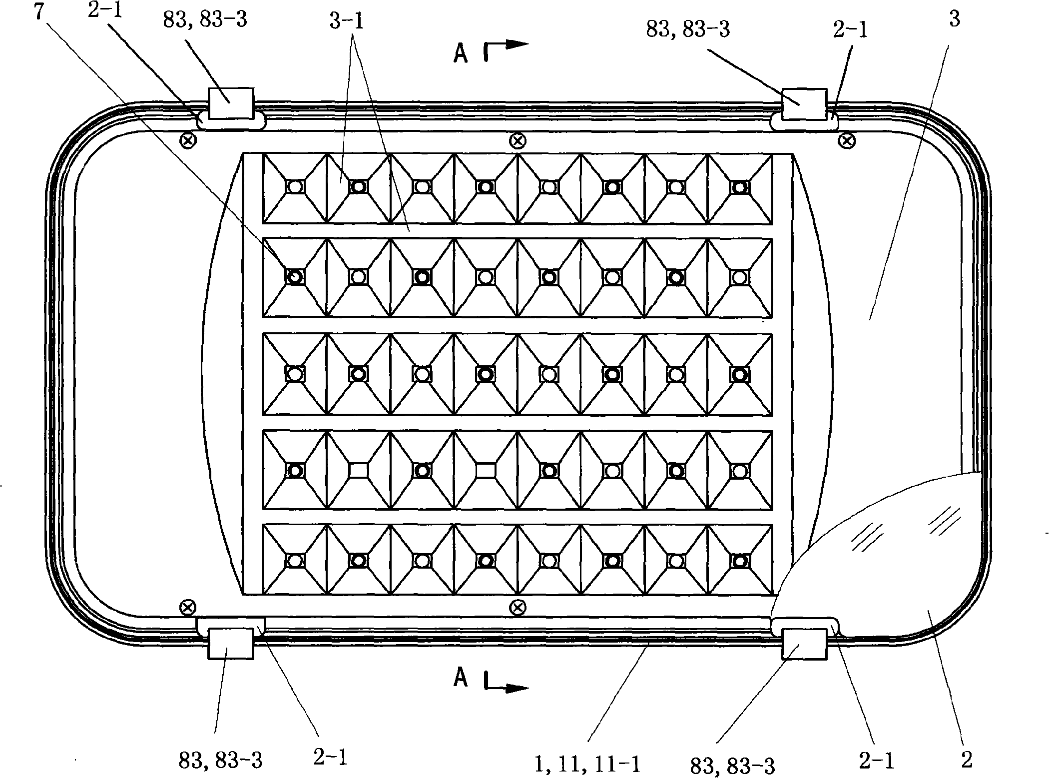
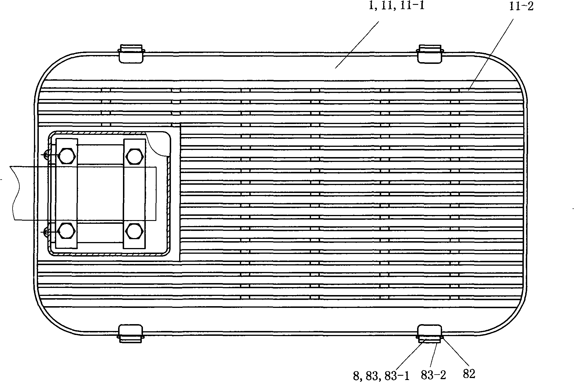
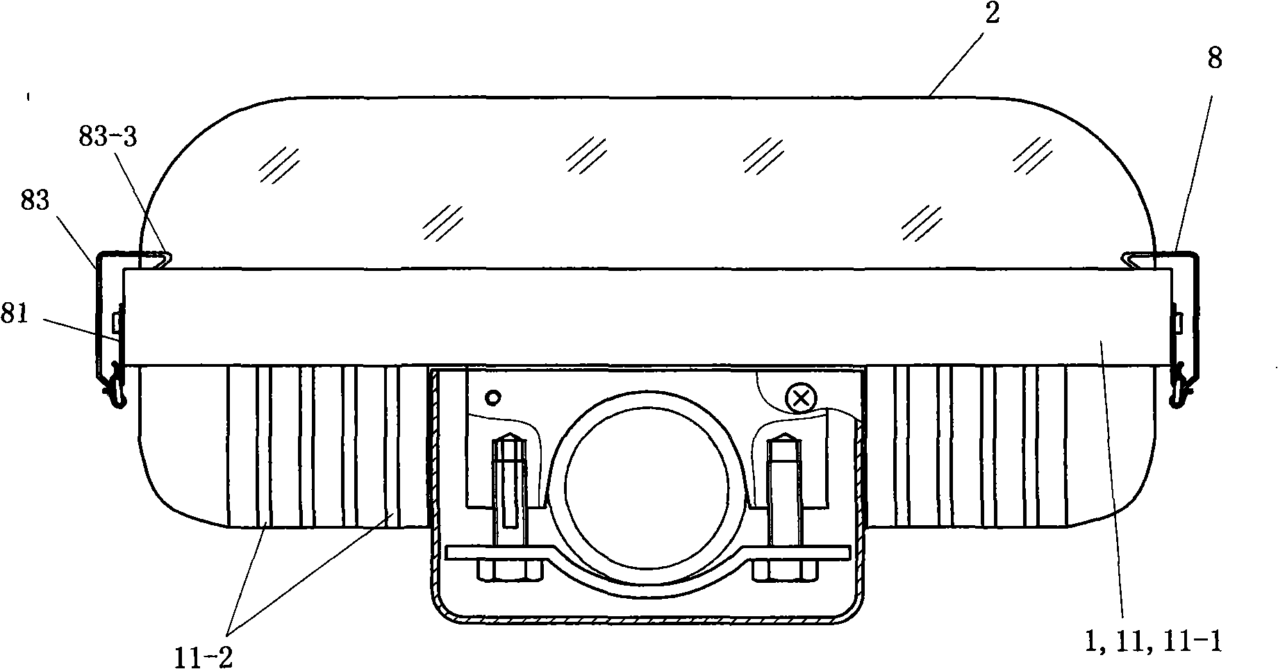
[0026] See Figure 1 to Figure 5 , Figure 8 As shown in Fig. 9, the high-power LED street lamp of this embodiment includes: an aluminum metal heat dissipation base 1, a transparent cover 2, a reflective panel 3, an aluminum substrate 4, an insulating barrier 5, an LED power drive circuit 6 and an LED bead array 7 . The LED lamp bead array 7 is composed of 5 rows of LED lamp beads. Both the aluminum substrate 4 and the insulation barrier 5 are strip-shaped, and each has five strips.

[0027] See Figure 4 The heat dissipation base 1 has an arcuate column housing 12-1, and the LED bead array 7 is arranged on the arcuate surface of the arcuate column housing 12-1.

[0028] See Figure 7 , Figure 4 and Figure 5 , The reflective panel 3 is an aluminum metal panel formed by one stamping after being coated with a reflective film. The reflective panel 3 has an arcuate surface ( Figure 4The reflective part 3-1 matched with the circular arc face upward); the reflective part...


PUM


Abstract

The invention relates to a high-power LED road lamp including a metallic heat radiation base panel, a reflecting, a LED lamp bead array and LED electric power drive circuit; the heat radiation base panel has a arch column casing, the LED lamp bead array is arranged on circular arc surface of the arch column casing; the reflecting panel has a reflecting section matching with arch column casing circular arc surface of the heat radiation base panel; the reflecting section mainly comprises panel bodies array with quadrangular frustum casing shape, and lamp bead holes are arranged at center of each panel body with quadrangular frustum casing shape; each LED lamp bead of the LED lamp bead array is in the lamp bead hole with quadrangular frustum casing shape corresponding with the reflecting section of the reflecting panel. In use, according to the invention, light reflected by the reflecting section of the reflecting panel forms a rectangular light beam to project on road, which achieves effect of uniformly irradiating reflection ray on road; the whole configuration of the reflecting section of the reflecting panel is crown face, which is favor for extending illumination area of road lamps.

Description

technical field [0001] The invention relates to a high-power LED street lamp. Background technique [0002] LED street lights are light-emitting diode street lights. Chinese patent document CN1821651A discloses a high-power LED street lamp, which includes a heat dissipation base. At least three connected LED lights are embedded in the concave bottom of the heat dissipation base. The exterior corresponding to the bottom surface has a specially designed strip heat sink. The LED lamp head is sleeved with a corresponding lens. A lens fixing cover is sandwiched between the heat dissipation base and the light transmission cover. Corresponding to the number of lens holes, the end of the lens is fixed through the corresponding lens holes. [0003] The disadvantages of the above-mentioned prior art are that the lens is used to scatter the light emitted by the LED lamp, which is costly, complicated in structure, and inconvenient for installation. Contents of the invention [0004...

Claims


Application Information

Patent Timeline
IPC IPC(8): F21S8/00F21V29/00F21V7/04F21V21/00F21V23/00F21W131/103F21Y101/02F21V29/70F21Y107/20F21Y115/10
CPCY02B20/72
Inventor 黄爱国
Owner 黄爱国
Why Eureka
Try Eureka