Roll bending device

A technology of bending rolls and installation positions, applied in the direction of counter pressure devices, metal rolling, manufacturing tools, etc., can solve problems such as weak supports, achieve simple design, reliable design, and avoid high load effects

Inactive Publication Date: 2008-10-08
SIEMENS VAI METALS TECHNOLOGIES GMBH & CO
View PDF0 Cites 8 Cited by
  • Summary
  • Abstract
  • Description
  • Claims
  • Application Information

AI Technical Summary

Problems solved by technology

[0010] It is an object of the present invention to overcome the problem of weaker support of the work roll chocks when rolling thicker material using existing curved block systems and to allow support of side loads

Method used


Image

  • Roll bending device
  • Roll bending device
  • Roll bending device

Examples


Embodiment Construction

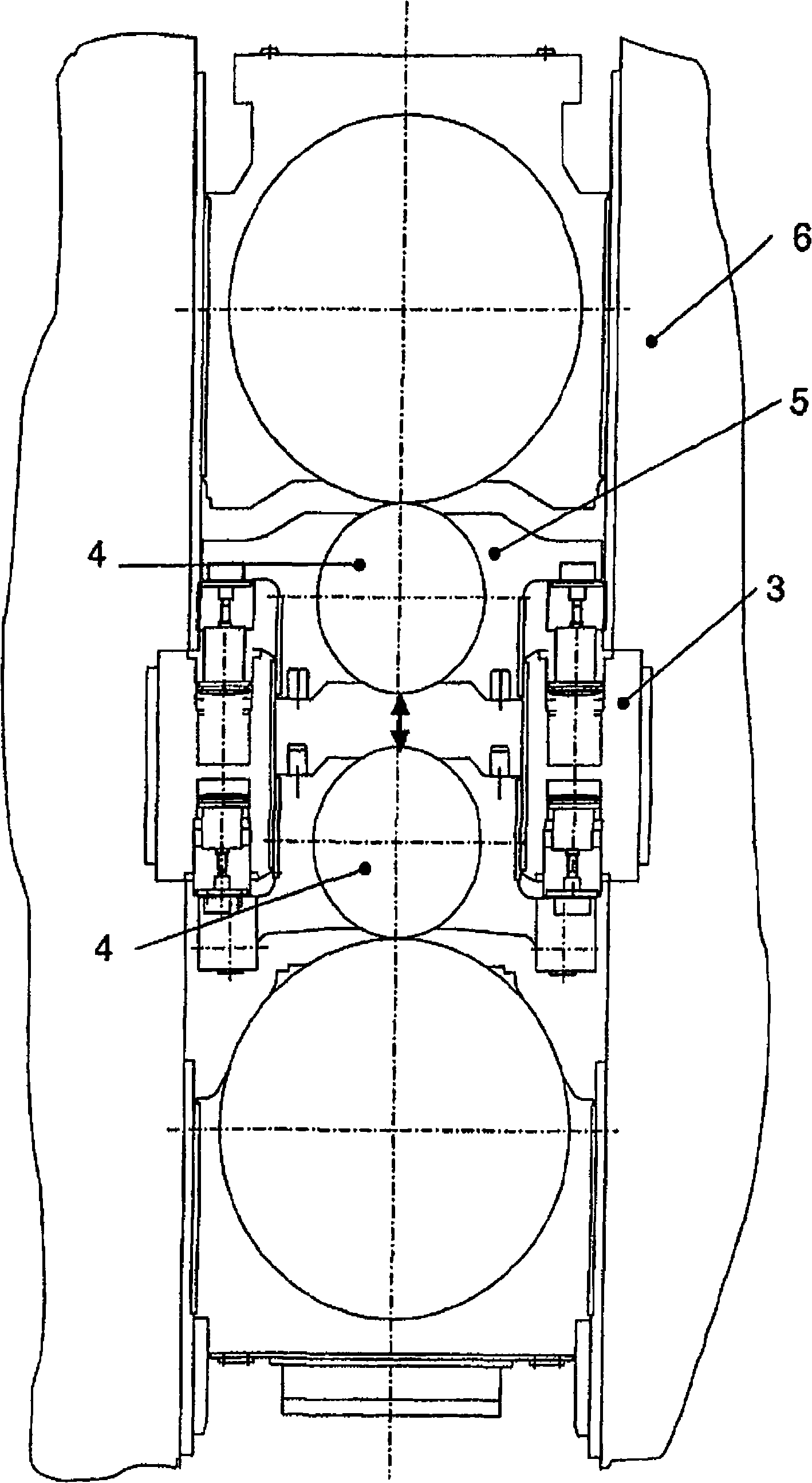
[0038] figure 1 The rolling stand shown is known from the prior art. The bending block is fixed to the roll stand frame 6 and is acting against the roll chock 5 to allow the roll 4 to bend. Especially when rolling or rolling thick materials with a large roll distance, the contact length between the roll chocks 5 at the bending block 3 is small, so that the roll chocks 5 are particularly in the presence of lateral loads. Insufficient and possible damage. This can lead to serious injury or substantially increased maintenance effort.

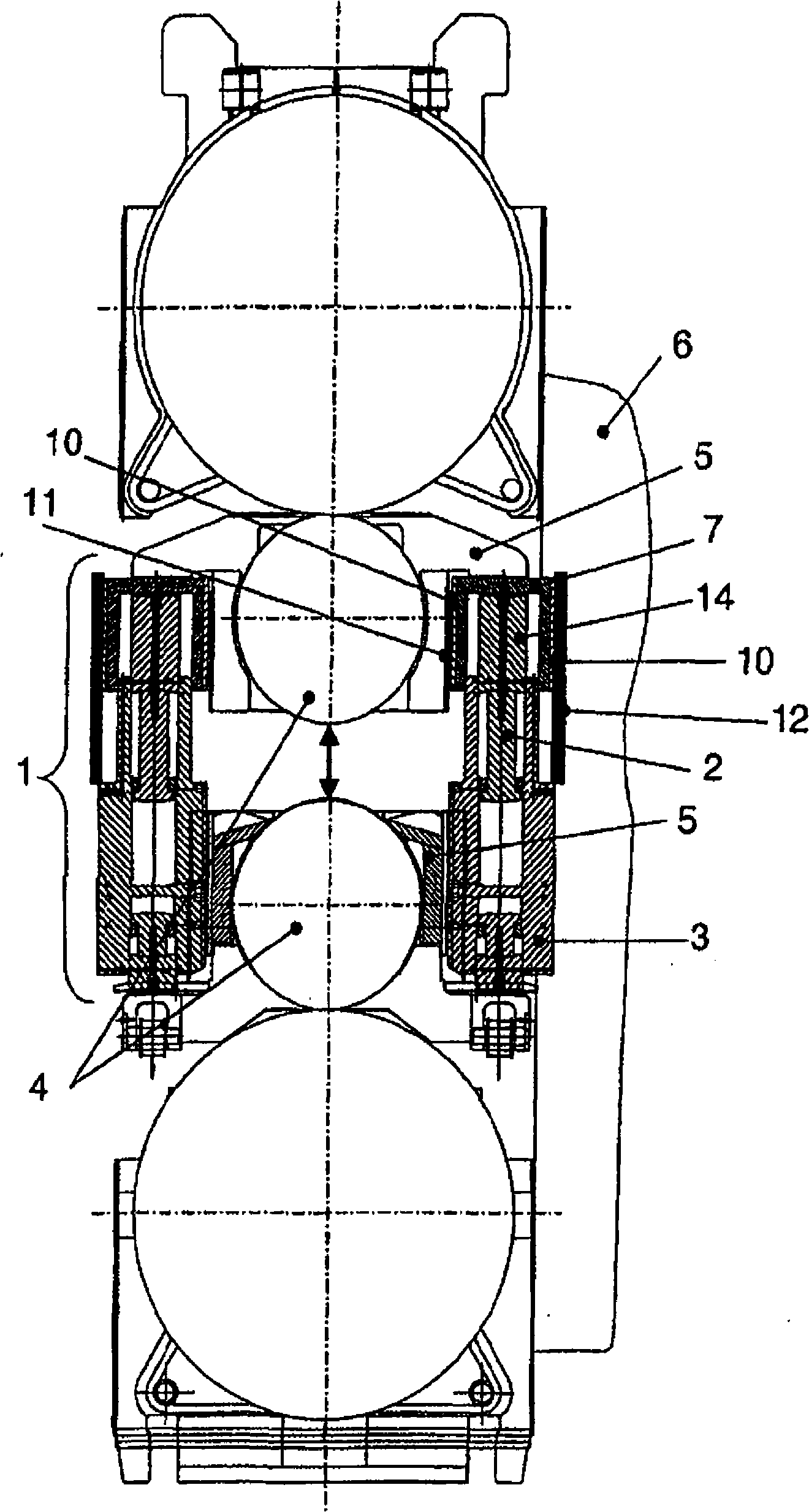
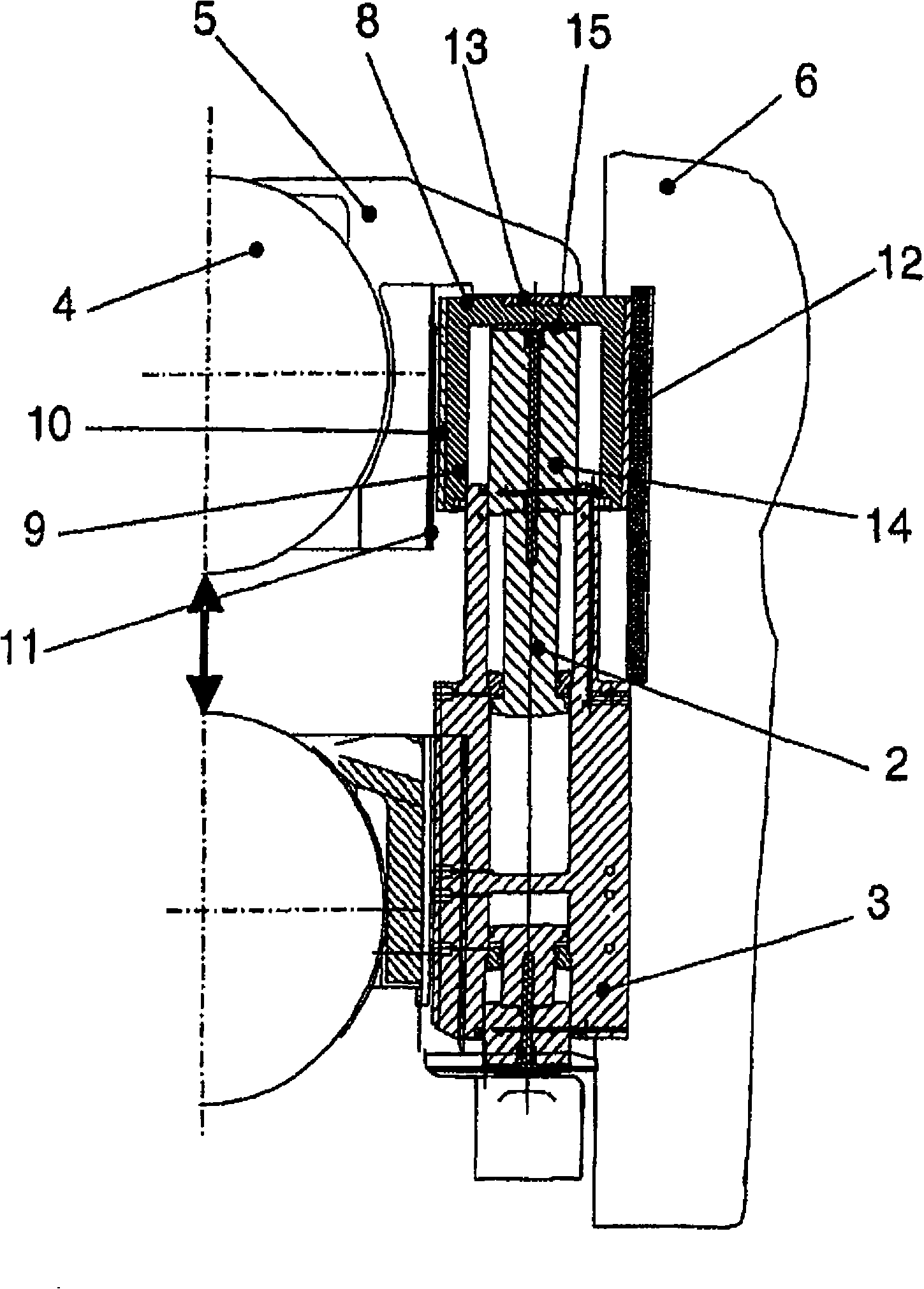
[0039] figure 2 A 4-high rolling stand with a bending device according to the invention is shown. The bending block 3 is fixable to the roll stand frame 6 and comprises at least one piston 2 generating the bending force. The bending force is transmitted to the roll chock 5 through the thrust piece 14 and the extension piece 7 . A thrust member 14 is connected to the piston 2 . The extension can move up and down together with the thrust memb...


PUM


Abstract

The invention relates to a roll bending device for the control of profile and flatness in the rolling of metal plates or strips. In particular the invention relates to the well known principle of roll bending by using hydraulic cylinders to modify the load distribution between rolls of a rolling mill stand and a rolled stock e.g. a metal plate or a strip in order to control the profile and flatness of the metal plate or strip. A special design to allow safe roll bending even at large roll gauges is presented. The new design allows safe operation even at large roll gauges and high side loads.

Description

technical field [0001] The invention relates to a roll bending device for profile and flatness control in material rolling. In particular, the present invention relates to the well-known principle of roll bending by the use of hydraulically actuated pistons to adjust the load distribution between the rolling stand and the rolled material, such as sheet metal or strip, in order to control the Profile and flatness of sheet or metal strip. It is known to bend the work rolls of a rolling stand which may have an additional pair of spare rolls (4-high rolling stand) or an additional pair of spare and intermediate rolls (6-high rolling stand). [0002] Further, the present invention relates to a rolling stand with at least one pair of rolls pivoting in roll chocks and arranged in a roll stand frame, with at least one hydraulically actuated piston arranged in a bending block , for roll bending in order to allow control of profile and flatness during the rolling of metal strip or she...

Claims


Application Information

Patent Timeline
Patent Type & Authority Applications(China)
IPC IPC(8): B21B29/00
CPCB21B29/00B21B37/38
Inventor B·库帕
Owner SIEMENS VAI METALS TECHNOLOGIES GMBH & CO
Why Eureka
Try Eureka