Clamping head for optical fibre splicer
An optical fiber splicer and collet technology, which is applied to the coupling of optical waveguides and other directions, can solve the problems of complicated operation, insufficient protection of bare fibers, and long splicing operation time, so as to achieve the effect of reliable bonding and multiple protection.
Inactive Publication Date: 2008-10-15
JIANGSU UNIKIT OPTICAL TECH
View PDF0 Cites 5 Cited by
- Summary
- Abstract
- Description
- Claims
- Application Information
AI Technical Summary
Problems solved by technology
At present, the installation of optical fiber cables for optical fiber connection sub-products mainly uses special tools to push the bare fiber by pressing the bent optical fiber sheath, so as to ensure the bonding of the optical fiber surface, and then rely on the single-point clamping device set in the sleeve Tight, the special tool cannot guarantee sufficient bonding force of the optical fiber, especially when the surface of the bare fiber is defective, it is even more difficult to ensure the true bonding of the fiber surface, and it cannot effectively prevent the rotation of the optical fiber cable. When an accidental force is applied during installation or use, it cannot fully protect bare fiber
There is also a collet used for optical fiber connectors, which is provided with an equal-tapered helical surface on the surface of the locking head of the collet cylinder. Although this structure has reliable performance and automatic anti-rotation, it is complicated to operate during the splicing process. Long operation time
Method used
View moreImage
Smart ImageViewing Examples

Examples
Embodiment Construction
Login to View More PUM
 Abstract
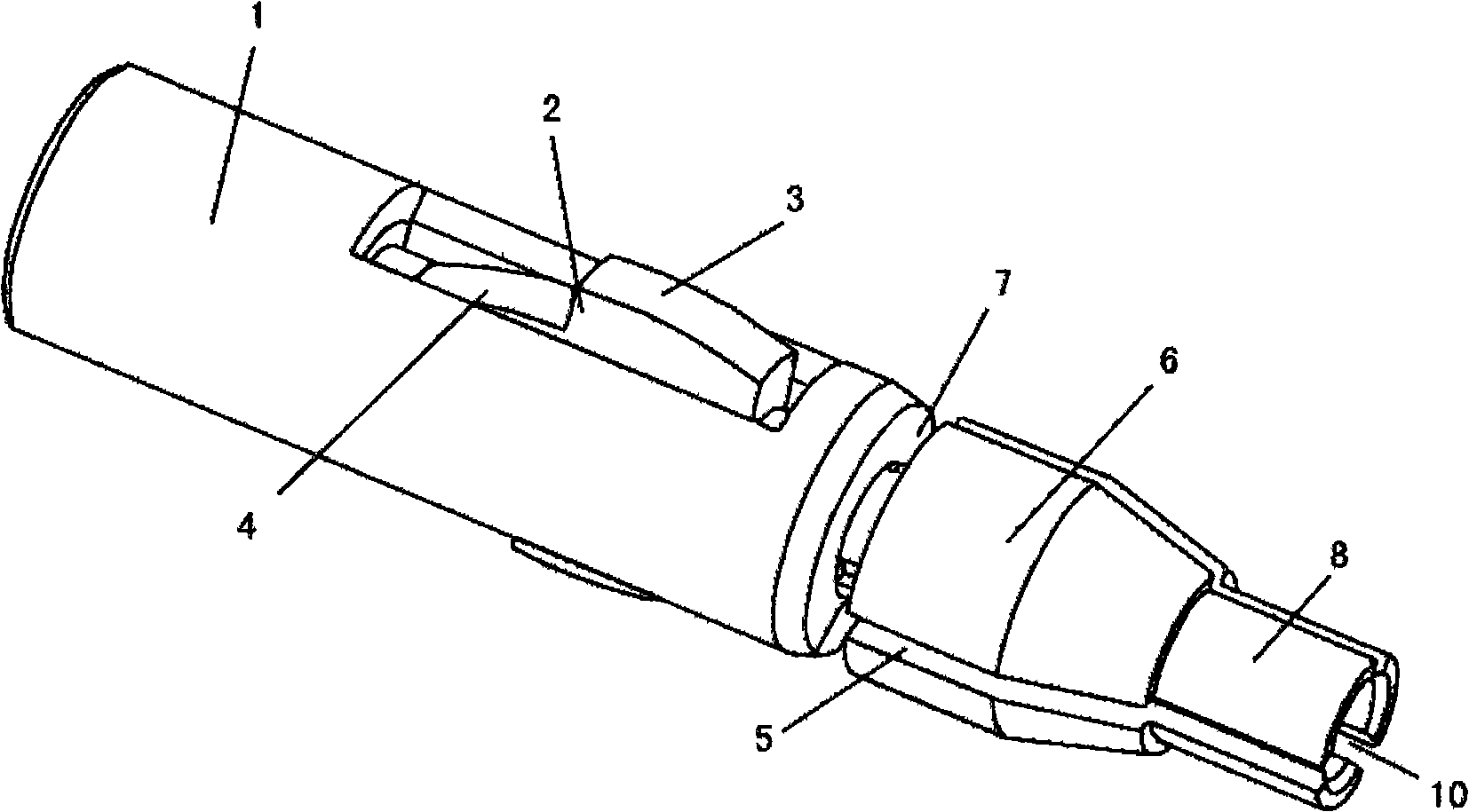
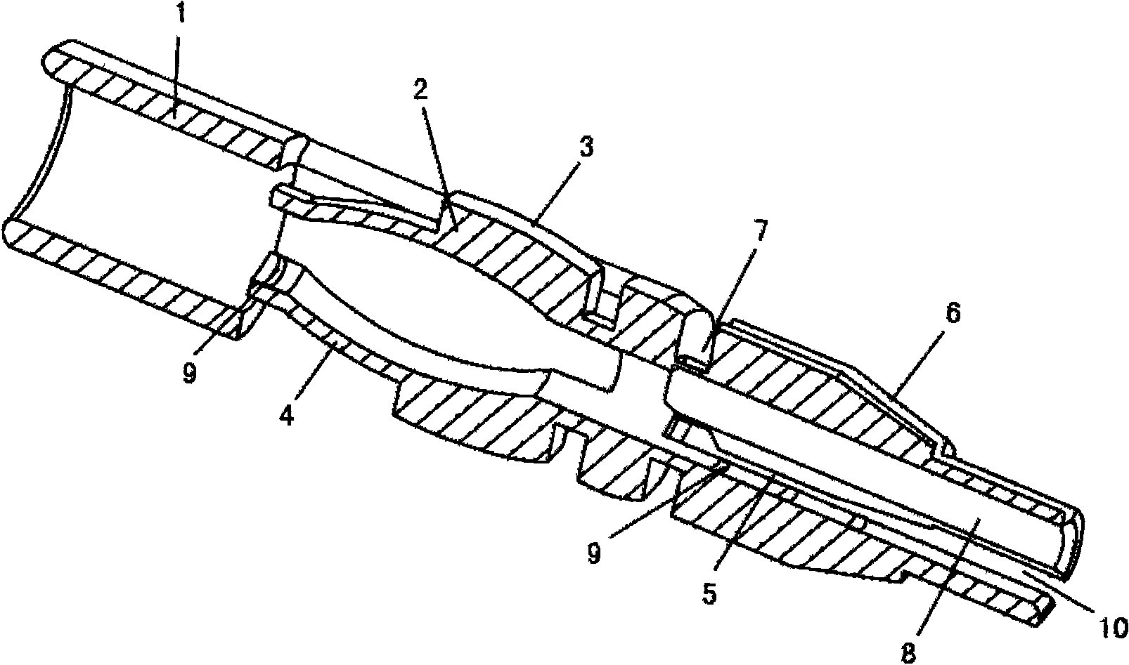
The invention discloses a collet used for a splice, comprising a cylindrical body provided with an optical fiber line hole, one end of the cylindrical body is provided with at least two locking heads divided by a lock groove, while the other end is provided with at least one spatula, the upper end face of the body of the spatula is an arch surface which can be extended by pressure, and the arch surface is higher than the external surface of the cylindrical body. Compared with the prior art, the collet has at least one spatula arranged on the front end of the cylindrical body, the upper end face of the body of the spatula is the arch surface which can be extended by the pressure, and the arch surface is higher than the external surface of the cylindrical body. When installed, an optical fiber line passes through the optical fiber line hole; an ejector sleeve of an optical-fiber junction group is pushed, when the ejector sleeve is pushed to the position of the spatula, the back arch surface of the spatula is pressed down; as the spatula head of the spatula is closely attached to the surface of the optical fiber line, and the arch surface of the body of the spatula is pressed to extend, so that the optical fiber line is pushed forward automatically, thereby guaranteeing the joint of fiber surfaces is powerful and reliable.
Description
Collets for fiber optic splices technical field The invention relates to a component for an optical fiber connector, in particular to a chuck for an optical fiber connector. Background technique At present, the installation of optical fiber cables for optical fiber connection sub-products mainly uses special tools to push the bare fiber by pressing the bent optical fiber sheath, so as to ensure the bonding of the optical fiber surface, and then rely on the single-point clamping device set in the sleeve Tight, the special tool cannot guarantee sufficient bonding force of the optical fiber, especially when the surface of the bare fiber is defective, it is even more difficult to ensure the true bonding of the fiber surface, and it cannot effectively prevent the rotation of the optical fiber cable. When an accidental force is applied during installation or use, it cannot Fully protect bare fibers. There is also a collet used for optical fiber connectors, which is provided wit...
Claims
Login to View More Application Information
Patent Timeline
 Patent Type & Authority Applications(China)
IPC IPC(8): G02B6/38
Inventor 吕根良黄金安
Owner JIANGSU UNIKIT OPTICAL TECH