Plug-in device for electrical connection

A plug-in device and electrical connection technology, applied in the direction of contact parts, etc., can solve the problems of large contact area, easy to loose, not strong enough, etc., and achieve the effect of overcoming small force, not easy to loose, and tight fit

Inactive Publication Date: 2008-10-15
PHOENIX ASIAN PACIFIC ELECTRIC NANJING +1
View PDF1 Cites 10 Cited by
  • Summary
  • Abstract
  • Description
  • Claims
  • Application Information

AI Technical Summary

Problems solved by technology

It can be seen from the disclosed technical scheme that the stainless steel shrapnel realizes the application of external force through the contact between its top and the surface of the copper terminal, but the strength is not strong enough. In addition, the contact between the positioning clip of the copper terminal and the end surface to be connected Large area, prone to loosening

Method used


Image

  • Plug-in device for electrical connection
  • Plug-in device for electrical connection
  • Plug-in device for electrical connection

Examples


Embodiment 1

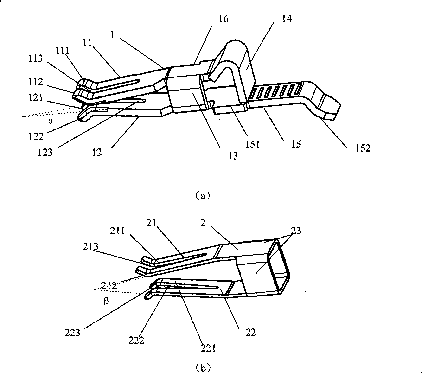
[0017] Embodiment 1: as figure 1 As shown, the plug-in device for electrical connection in this embodiment includes a metal piece 1 and a spring steel sheet 2 surrounding the outer periphery of the metal piece 1, wherein the metal piece 1 includes two opposite elastic side legs 11, 12, two The elastic side legs 11, 12 are connected by laths 13; the spring steel sheet 2 includes two opposite clip side parts 21, 22, and one end of the two clip side parts 21, 22 is connected by a cladding ring piece 23; the cladding ring piece 23 is corresponding to the position of the lath 13, and is coated on the tail portion 16 of the metal part 1 where the lath 13 is located. The other ends of the two clamping side portions 21, 22 and the outer sides of the contact portions 18 of the two elastic side legs 11, 12 are respectively Contact, the two clip side parts 21, 22 are straight shapes, such as Figure 5 As shown, the two clip side portions 21, 22 can also be curved. The tail portion 16 o...

Embodiment 2

[0018] Embodiment 2: as figure 2 , image 3 As shown, the plug-in device for electrical connection in this embodiment includes a metal piece 1 and a spring steel sheet 2 surrounding the outer periphery of the metal piece 1, wherein the metal piece 1 includes two opposite elastic side legs 11, 12, two The elastic side legs 11, 12 are connected by laths 13; the spring steel sheet 2 includes two opposite clip side parts 21, 22, and one end of the two clip side parts 21, 22 is connected by a cladding ring piece 23; the cladding ring piece 23 is corresponding to the position of the lath 13, and is coated on the tail portion 16 of the metal part 1 where the lath 13 is located. The other ends of the two clamping side portions 21, 22 and the outer sides of the contact portions 18 of the two elastic side legs 11, 12 are respectively Contact, the two clip side parts 21, 22 are straight shapes, such as Figure 5 As shown, the two clip side portions 21, 22 can also be curved. The elas...

Embodiment 3

[0020] Embodiment 3: as Figure 4 As shown, the plug-in device for electrical connection in this embodiment has basically the same structure as that in Embodiment 2, except that the plug-in device in this embodiment does not have a bent portion 14 .


PUM


Abstract

The invention discloses a plug device used for electrical connection, which comprises a metal piece and an elastic steel slice surrounding the periphery of the metal piece, wherein, the metal piece comprises two elastic side lags which are arranged oppositely and connected by a lath; the elastic steel slice comprises two clamping side parts which are arranged oppositely and one end of one clamping side part is connected with one end of the other clamping side part by a coating ring plate; the position of the coating ring plate is corresponding to the position of the lath and the coating ring plate coats the tail part of the metal piece and the other end of the two clamping side parts contacts the outer side of the contacting parts of the two elastic side lags respectively. The device has the advantages that: (1) the elastic steel slice and the metal piece are in close fit, which overcomes the disadvantage that the acting force of the elastic steel slice in the prior art is little; (2) the elastic side lags of the metal piece are provided with open grooves, which leads to two-points connection between the elastic side lags and components to be connected and prevents looseness; the grooves are good for heat elimination and the plug device is especially applicable to occasions where through current is relatively large.

Description

1. Technical field [0001] The invention relates to an electrical connection device, in particular to a plug-in device connected with electrical components to be connected in a terminal block. 2. Background technology [0002] The function of the terminal is to connect electrical devices that are independent of each other to form electrical contact or connection, that is, to form a conductive connection between one electrical component and another electrical component. For example, in the field of printed circuit board terminals, the connector that connects the wires to the socket on the printed circuit board is an important type. It must not only ensure the reliability of the electrical connection, but also ensure the ability to perform multiple It can be plugged and unplugged without degrading the effect of its connection. The metal part of this type of connector is generally made of copper material. Copper material has excellent electrical conductivity, but its elasticity...

Claims


Application Information

Patent Timeline
Patent Type & Authority Applications(China)
IPC IPC(8): H01R13/18
Inventor 伍都・豪伯
Owner PHOENIX ASIAN PACIFIC ELECTRIC NANJING
Why Eureka
Try Eureka