Backlight module group and its optical plate

A technology of backlight module and optical plate, applied in optics, optical elements, nonlinear optics, etc., can solve the problem of uneven light output of backlight module 100, and achieve the effect of improving light output uniformity and light output uniformity.

Inactive Publication Date: 2008-10-22
HONG FU JIN PRECISION IND (SHENZHEN) CO LTD +1
View PDF0 Cites 0 Cited by
  • Summary
  • Abstract
  • Description
  • Claims
  • Application Information

AI Technical Summary

Problems solved by technology

The matching design of the light-emitting diode 105 and the reflector 106 can eliminate the bright area directly above the

Method used


Image

  • Backlight module group and its optical plate
  • Backlight module group and its optical plate
  • Backlight module group and its optical plate

Examples


Embodiment Construction

[0020] The backlight module and its optical plate of the present invention will be further described in detail below in conjunction with the drawings and embodiments.

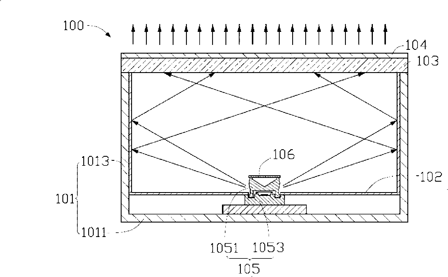
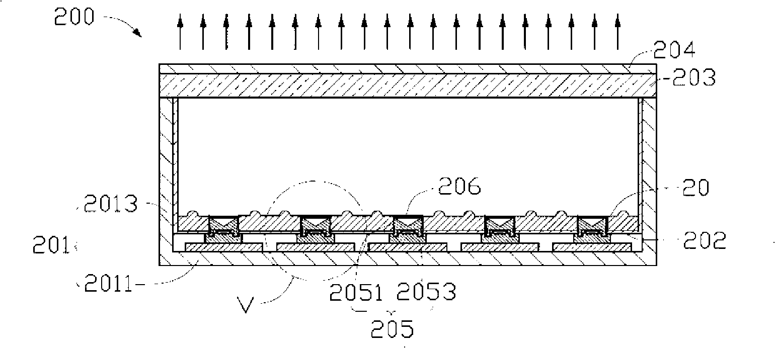
[0021] See figure 2 , The backlight module 200 of the first preferred embodiment of the present invention is shown, which includes a frame 201, a diffusion plate 203, a plurality of point light sources 205, an optical plate 20 and a reflective sheet 206. The frame 201 includes a bottom plate 2011 and four sidewalls 2013 vertically extending from the edge of the bottom plate 2011 to one side thereof. The four side walls 2013 are connected to each other and form a cavity (not shown in the figure) together with the bottom plate 2011 for accommodating the point light source 205 and the optical plate 20. The diffusion plate 203 is disposed on the top of the side walls 2013.

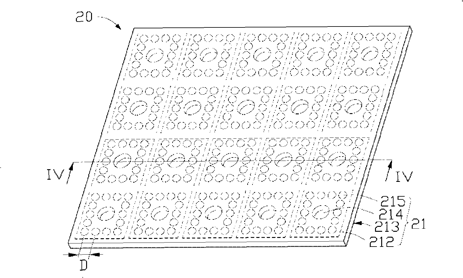
[0022] See also image 3 versus Figure 4 The optical plate 20 has a square shape and includes a plurality of optical plate units 21 arranged clo...


PUM

PropertyMeasurementUnit
Spherical radiusaaaaaaaaaa
Heightaaaaaaaaaa

Abstract

The invention discloses an optical plate which comprises at least one optical plate unit, wherein, the optical plate unit comprises a light leaving surface and a bottom surface opposite to the light leaving surface. The light leaving surface is provided with a plurality of protuberances, and the bottom surface is provided with a light source receiving part. The invention also provides a backlight module adopting the optical plate. The backlight module and the optical plate thereof have the advantage of even light output.

Description

Technical field [0001] The present invention relates to a backlight module and its optical plate, in particular to a backlight module and its optical plate for liquid crystal display. Background technique [0002] Since the liquid crystal of the liquid crystal display panel does not have light-emitting characteristics, in order to achieve the display effect, it is necessary to provide a surface light source device, such as a backlight module, for the liquid crystal display panel. The function of the backlight module is to supply a surface light source with sufficient brightness and uniform distribution to the LCD panel. [0003] See figure 1 , Shown is an existing backlight module 100, which includes a frame 101, a reflective plate 102, a diffuser plate 103, a prism sheet 104 and at least one light emitting diode 105. The frame 101 includes a bottom plate 1011 and a plurality of side walls 1013 vertically extending from the edge of the bottom plate 1011 to one side thereof. The ...

Claims


Application Information

Patent Timeline
IPC IPC(8): G02B6/00G02F1/13357G02F1/1335
CPCG02B6/0021G02B6/003G02B6/0031G02B6/0038G02F1/133603G02F1/133609
Inventor 章绍汉
Owner HONG FU JIN PRECISION IND (SHENZHEN) CO LTD
Why Eureka
Try Eureka