
Iron core construction with unequal intersecting surface for working at saturated magnetization zone

A superconducting current limiter and core-type technology, which is applied in the field of core structure, can solve the problems of normal operation of the power grid, reduce the voltage drop of the current limiter, and fail to reach the saturation depth, etc., and achieve the goal of eliminating adverse effects and reducing the impact Effect

Inactive Publication Date: 2012-05-09
北京云电英纳超导电力技术有限公司 +1
View PDF0 Cites 0 Cited by
  • Summary
  • Abstract
  • Description
  • Claims
  • Application Information

AI Technical Summary

Problems solved by technology

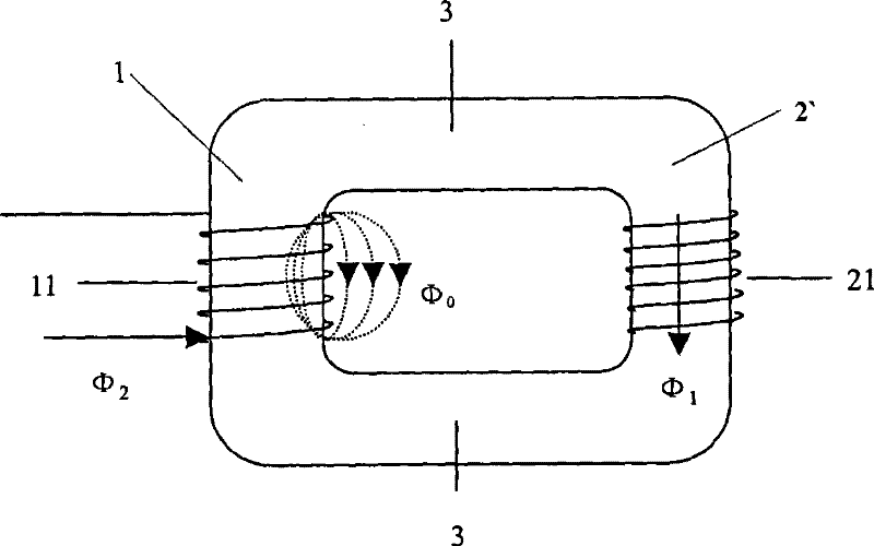
If the excitation current is increased, the flux leakage will increase accordingly. Due to the increase of the flux leakage, the ratio of the magnetic potential on the excitation section 1' to the total magnetic potential generated by the winding will also increase, so the working section 2' Compared with the excitation section 1', the magnetic potential on the surface decreases, and it needs to increase the excitation current when it reaches a certain degree of saturation, and even increasing the excitation current is difficult to achieve
[0004] Whether it is a saturated reactor or a saturated core type superconducting fault current limiter, due to the existence of magnetic flux leakage, the working section 2' cannot reach the saturation depth required by the design or cannot enter the saturation state at all. For a saturated core type superconducting current limiter, increasing the steady-state impedance of the current limiter will increase the reactive power in the grid and reduce the flexibility. The voltage drop on the load behind the current limiter has a certain impact on the normal operation of the power grid

Method used


Image

  • Iron core construction with unequal intersecting surface for working at saturated magnetization zone
  • Iron core construction with unequal intersecting surface for working at saturated magnetization zone
  • Iron core construction with unequal intersecting surface for working at saturated magnetization zone

Examples


Embodiment Construction

[0033] The specific implementation manner of the present invention will be described below in conjunction with the accompanying drawings.

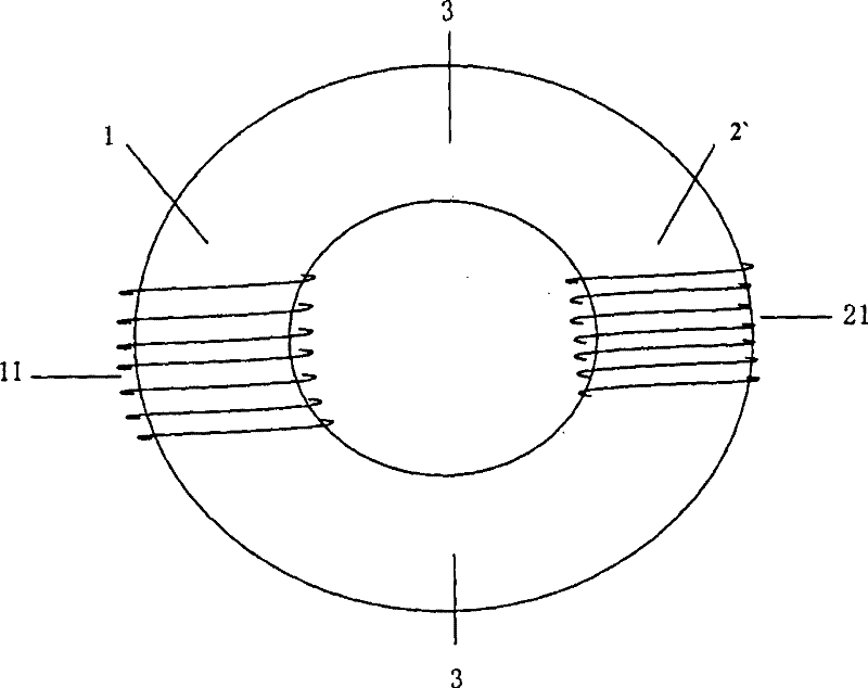
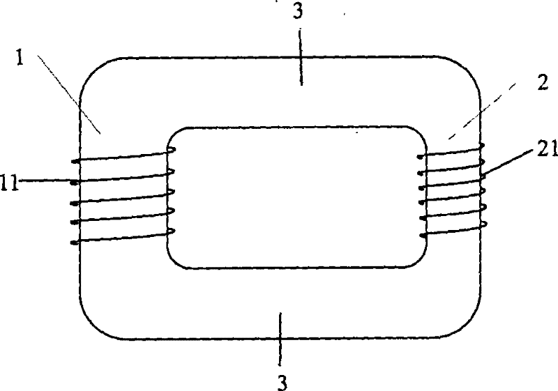
[0034] Fig. 2-1(a) is a schematic diagram of an embodiment of the present invention with a square-shaped iron core structure with unequal cross-section for working in the magnetic saturation region and the working winding 21 is wound on a position opposite to the magnetic conducting winding 11, which provides a The unequal cross-section core structure is used to work in the magnetic saturation area. The core is a closed core, including the excitation section 1, the working section 2 and the magnetic conduction section 3. Among them, the cross-sectional area of ​​the iron core of the excitation section 1: the core of the working section 2 Cross-sectional area = 1.01 ~ 10, the preferred value range of this ratio is 1.2 ~ 3, the cross-sectional area of ​​the iron core of the excitation section 1: the cross-sectional area of ​​the magnetic sect...


PUM

PropertyMeasurementUnit
areaaaaaaaaaaa

Abstract

The invention relates to an unequal sections iron core structure of saturated core superconducting current limiter. The iron core is a closed iron core and comprises an excitation section, a working section and a magnetic conduction section. The iron core is characterized in that: the cross-section area ratio of an excitation section iron core and a working section iron core is equal to between 1.01 and 10, the cross-section area ratio of the excitation section iron core and a magnetic conduction section iron core is equal to between 1 and 10, and cross-section area of the magnetic conduction section iron core is more than that of the working section iron core, and less than or equal to that of the excitation section iron core. The structure reduces the influence of magnetic leakage on the iron core by changing the structural shape and the dimension of the iron core further to cause magnetic potential on the iron core to be redistributed, can ensure that the iron core reaches the designed saturation under the condition of not changing or reducing excitation magnetic potential, and is particularly applicable to electromagnetic equipment, iron cores of which have magnetic biasing or work in deep saturation regions, such as saturable core superconducting fault current limiters and saturable reactors and so on.

Description

technical field [0001] The present invention relates to a special iron core structure, especially the unequal cross-section iron core structure used in the magnetic saturation region, especially suitable for the electromagnetic equipment where the iron core has bias magnetism or the iron core works in the deep saturation region, such as saturated iron core type superconductor Fault current limiter and saturable reactor etc. Background technique [0002] Saturated iron core type superconducting fault current limiter and saturated reactor are both electromagnetic equipment composed of iron core, working winding and excitation winding. The working principle is basically the same, that is, by changing the excitation current in the excitation winding to adjust the saturation of the iron core. Then change the inductance value of the working winding wound on the iron core post to realize its regulation or current limiting function. Such as Picture 1-1 and Figure 1-2 As shown, t...

Claims


Application Information

Patent Timeline
Patent Type & Authority Patents(China)
IPC IPC(8): H01F3/00H01F27/24H01F41/02
CPCY02E40/69
Inventor 龚伟志信赢曹正建张敬因牛潇晔任安林孙树英高永全
Owner 北京云电英纳超导电力技术有限公司
Learn More