Manufacturing method of control device for low-voltage isolation technique

A technology control, low-voltage power grid technology, applied in circuit devices, emergency protection circuit devices, emergency protection circuit devices for limiting overcurrent/overvoltage, etc., can solve three-phase load imbalance, electric shock damage, failure to reach Design effects, etc.

Inactive Publication Date: 2010-07-28
陈家斌
View PDF0 Cites 0 Cited by
  • Summary
  • Abstract
  • Description
  • Claims
  • Application Information

AI Technical Summary

Problems solved by technology

[0002] In order to prevent personal contact, electric shock casualties of live metal conductors and electrical fire accidents caused by metal short-circuit grounding faults of phase lines, and to ensure the thermal stability of lines and equipment in operation; my country's current electrical design, construction and other relevant regulations have proposed that low-voltage Ground fault protection is installed in distribution lines; meanwhile, various types of protection devices such as leakage switches and residual current actions are generally installed in low-voltage distribution lines at home and abroad; however, in actual operation, they cannot achieve expected design effect
[0003] For example: (1) When a phase wire metal short-circuit ground fault occurs in the line, the current size of the loop depends on the grounding resistance and soil resistance of the protective grounding wire, and an electrical fire is likely to occur immediately when the phase wire is grounded; (2) If the person touches the metal As a live conductor, the voltage that the human body bears is the phase line-to-ground potential. The current passing through the human body depends on the human body's own conditions (age, height, weight) and electric shock environmental conditions (high altitude, water, air humidity, etc.), whether personal safety can be guaranteed It is also related to the switching speed of the trip circuit, that is to say, when the human body touches the live conductor, it will be injured by electric shock. These ground fault currents will also cause the residual current relay to trip frequently, affecting the reliability of power supply
(3) In rural lighting circuits or distribution lines with many single-phase loads, it is very easy to cause unbalanced three-phase loads. At this time, a large zero-sequence current is bound to be generated, and a part of the zero-sequence current passes through the neutral line is neutralized, and the other part flows into the earth through the grounding wire of the neutral line to be consumed; similarly, when the insulation of the three-phase circuit is unbalanced to the ground, a large zero-sequence current will also be generated, and the zero-sequence current will pass through the neutral line of the earth. The ground wire of the line constitutes a closed loop to be consumed
[0004] Through the above analysis, the existing residual current relay has obvious technical performance defects, that is, the technical performance is not perfect; when the line has a phase line metal short-circuit ground fault, the ground fault loop current is large, and an electrical fire is likely to occur at the moment of grounding; When touching a live metal conductor, the human body bears a high voltage and a large current passes through the human body, and will be injured by an electric shock at the moment of electric shock; direct contact protection cannot be realized, and the safety of electric shock when the person touches a live metal conductor in the low-voltage power grid cannot be guaranteed, and Unable to control the loss of zero-sequence current leakage to ground and line-to-ground leakage current

Method used


Image

  • Manufacturing method of control device for low-voltage isolation technique
  • Manufacturing method of control device for low-voltage isolation technique
  • Manufacturing method of control device for low-voltage isolation technique

Examples


Embodiment Construction

[0016] The present invention will be further described in detail below in conjunction with the drawings and specific implementations:

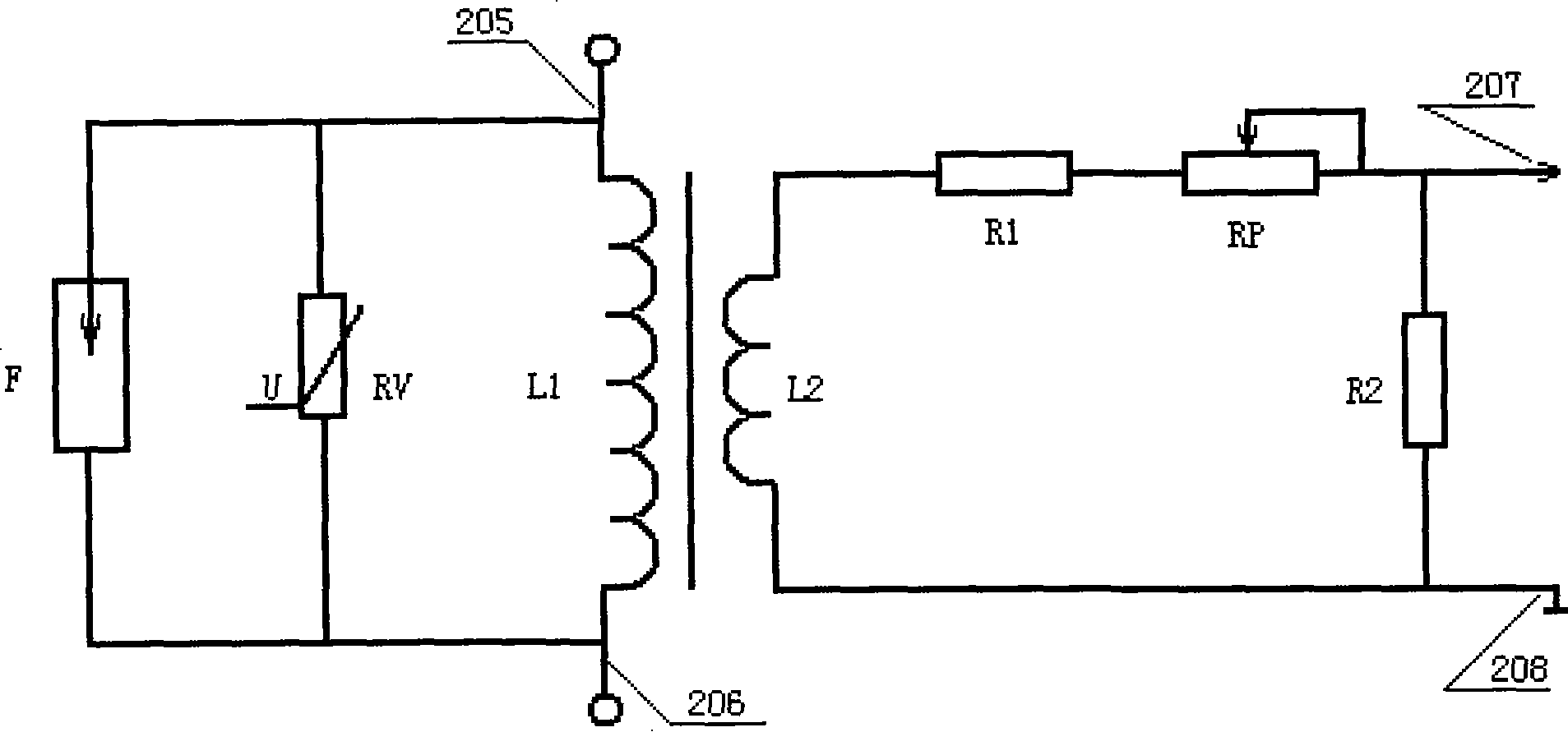
[0017] Such as figure 1 As shown, a low-voltage power grid isolation technology control device includes an overvoltage prevention device RV, a lightning protection device F, an isolation transformer with a primary winding L1 and a secondary winding L2, an adjustable resistor RP, a resistor R1 and Resistance R2;

[0018] Wherein, the primary winding L1 of the isolation transformer, the overvoltage prevention device RV, and the lightning protection device F are connected in parallel, and the head ends of the aforementioned components are connected to form the head end 205 of the low-voltage power grid isolation technology control device. The connected tail ends of the components constitute the tail end 206 of the low-voltage power grid isolation technology control device;

[0019] The secondary winding L2 of the isolation transformer is sequentially c...


PUM

PropertyMeasurementUnit
heightaaaaaaaaaa
electrical resistanceaaaaaaaaaa
impedanceaaaaaaaaaa

Abstract

The invention provides a low-voltage electric fence isolation technique control device and a method for manufacturing the same. The device comprises an overvoltage-proof device RV, a lightning-proof device F, a special isolation transformer having a primary winding L1 and a secondary winding L2, a tunable resistor RP, a resistor R1 and a resistor R2, wherein the primary winding L1 of the special isolation transformer, the overvoltage-proof device RV and the lightning-proof device F are connected in parallel; the secondary winding L2 of the special isolation transformer is connected in series orderly with the resistor R1, the tunable resistor RP and the resistor R2; the head end and the tail end of the resistor R2 are output ends of the isolation technique control device. The core of the method for manufacturing the device lies in the manufacture of the special isolation transformer, and mainly comprises two steps of manufacturing iron cores and winding coils. The low-voltage electric fence isolation technique control device can provide safety protection for personal electric shock, prevent electrical fire and reduce electric leakage loss.

Description

Technical field [0001] The invention relates to a manufacturing method of a safety protection device, in particular, to a low-voltage power grid isolation technology control device for isolation of a low-voltage power grid from the earth and a manufacturing method thereof. Background technique [0002] In order to prevent personal contact, electric shock and casualties of live metal conductors, and electrical fire accidents caused by phase line metallic short circuit and ground faults, and to ensure the thermal stability of lines and equipment in operation; my country’s current electrical design and construction specifications have all proposed Ground fault protection is installed in the distribution line; at the same time, various types of leakage switches, residual current action and other protection devices are generally installed in low-voltage distribution lines at home and abroad; however, they cannot reach Expected design effect. [0003] For example: (1) When a phase wire me...

Claims


Application Information

Patent Timeline
Patent Type & Authority Patents(China)
IPC IPC(8): H02H3/32H01F41/04H02H9/04H01F19/00H01F41/02H02H3/14
Inventor 陈家斌
Owner 陈家斌
Why Eureka
Try Eureka