Bobbin fixing device and bobbin removing device

A technology of fixing device and dismantling device, which is applied in the directions of transportation and packaging, transportation of filamentous materials, thin material processing, etc., can solve the problems of increased man-hours for loading and unloading spools and reduced operating efficiency, and achieves the effect of easy disassembly and simple structure.

Inactive Publication Date: 2008-10-22
BRIDGESTONE CORP
View PDF1 Cites 15 Cited by
  • Summary
  • Abstract
  • Description
  • Claims
  • Application Information

AI Technical Summary

Problems solved by technology

However, there is a problem that the number of man-hours for loading and unloading the bobbin increases, and the working efficiency decreases.

Method used


Image

  • Bobbin fixing device and bobbin removing device
  • Bobbin fixing device and bobbin removing device
  • Bobbin fixing device and bobbin removing device

Examples


no. 1 Embodiment approach

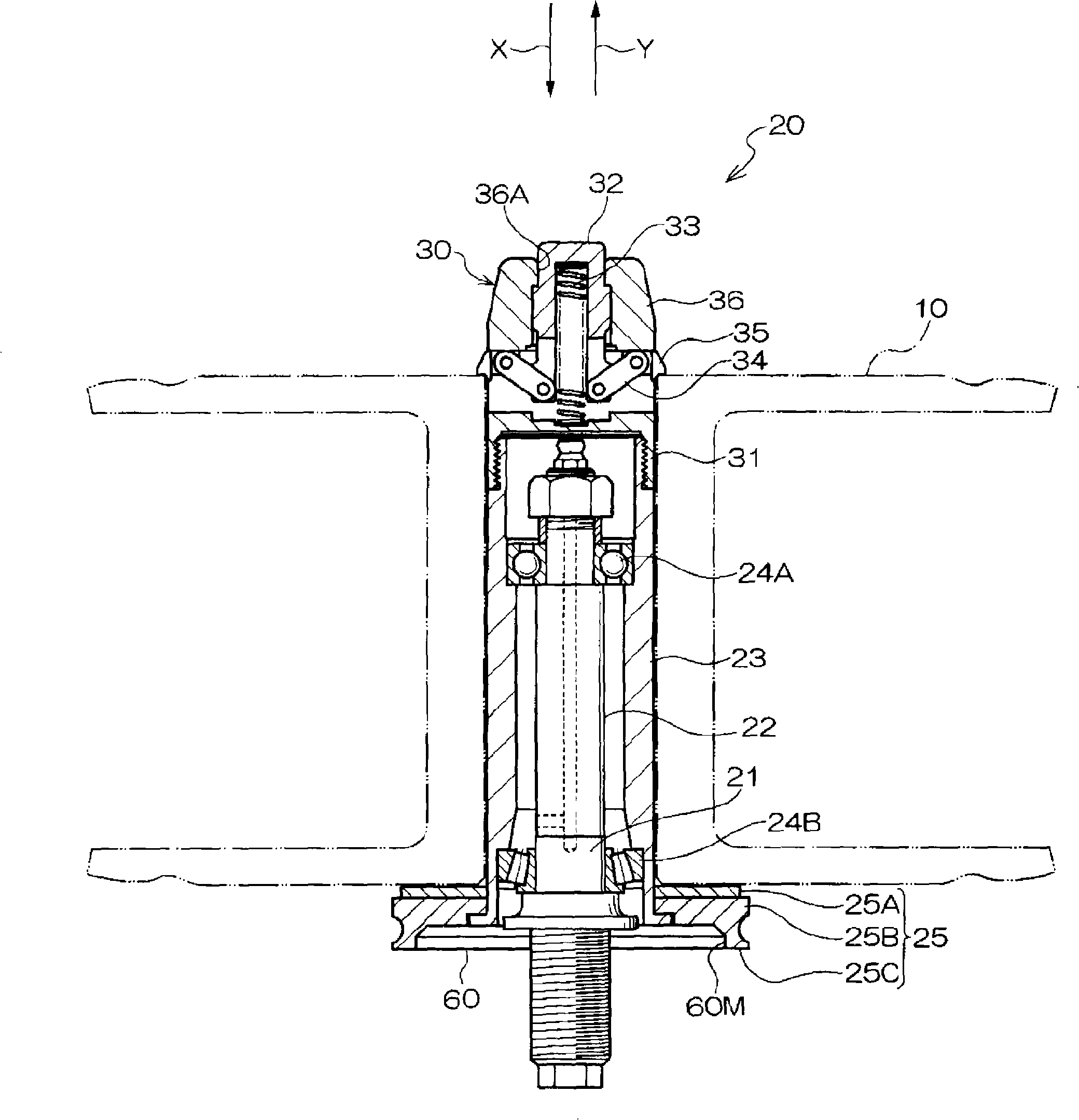
[0062] Next, a first embodiment of a bobbin removing device according to the present invention will be described with reference to the drawings. Such as Figure 6 The bobbin fixing device 20 of this embodiment shown is a device for fixing the bobbin 10 having the flange 10A and the shaft portion 10B, and has the same structure as the bobbin fixing device 20 of the present invention described above. In addition, the bobbin removal device 40 is a device for removing the bobbin 10 fixed to the bobbin fixing device 20 .

[0063] Such as Figure 6 As shown, the bobbin removal device 40 of this embodiment has a main body 42 , a holding arm 44 , and a movement allowing member 46 . The main body 42 includes a shaft portion 42A and a collar portion 42B. The shaft portion 42A is arranged on the extension line of the rotating shaft 23 of the bobbin fixing device 20 and is movable in the axial direction of the rotating shaft 23 . The shaft portion 42A has a flange portion formed on th...

no. 2 Embodiment approach

[0073] Hereinafter, a second embodiment of the bobbin removing device according to the present invention will be described with reference to the drawings. In this embodiment, the same reference numerals are attached to the same parts as those in the first embodiment, and detailed description thereof will be omitted.

[0074] The bobbin fixing device 20 of this embodiment is the same as that of the first embodiment. Such as Figure 11 As shown, the spool removal device 50 has a main body 52 , a retaining arm 54 and a movement permitting member 56 . The main body 52 includes a shaft portion 52A and a collar portion 52B. The shaft portion 52A is arranged on the extension line of the rotating shaft 23 of the bobbin fixing device 20 and is movable in the axial direction of the rotating shaft 23 . The shaft portion 52A has a flange portion formed on the lower side of the column. The collar portion 52B is disposed below the flange portion of the shaft portion 52A.

[0075] The c...


PUM


Abstract

The present invention provides a bobbin fixing device capable of fixing a bobbin easily with a simple structure and also provides a bobbin removing device capable of removing a bobbin readily with a simple structure. Stoppers 35 project from the level of the outer surface of a rotating shaft 23. Sloping surface of each stopper 35 is pressed by a bobbin 10, so that the stopper is moved to an inner position P2. The bobbin 10 is attached so as to position on a positioning member 25. When the bobbin 10 is brought into contact with the positioning member 25, each support 34B upwardly moves together with a release button 32 biased by a spring 33, so that one end of each arm 34A on the associated support 34B moves upward and the other end thereof close to the associated stopper 35 moves downward. Thus, each stopper 35 outwardly moves and projects until a restricting face 35C of the stopper 35 is brought into contact with the bobbin 10. At that time, a retaining face 35B of each stopper 35 is in contact with the top surface of the bobbin 10, thus restricting the movement of the bobbin 10 in the direction (Y direction) in which the bobbin 10 is removed from the rotating shaft 23.

Description

technical field [0001] The present invention relates to a bobbin holder for rotatably holding a bobbin for use on a winding machine, stranding machine or the like. Furthermore, the present invention also relates to a bobbin detaching device for detaching a bobbin from a bobbin fixing device that rotatably holds a bobbin used on a winding machine, a winding machine, or the like. Background technique [0002] Conventionally, when the wire is supplied to a winding machine, a stranding machine, etc., the wire is pulled out while rotating the bobbin on which the wire is wound, and therefore a bobbin fixing device that holds the bobbin in a rotatable manner is used. As the method of fixing the bobbin, there are methods using power such as air and electricity, and manual mechanical fixing methods such as a slot lever method, a screw method, and a dowel method. [0003] In the above-mentioned fixing method, when a power such as air or electric power is used, there is a problem that...

Claims


Application Information

Patent Timeline
Patent Type & Authority Applications(China)
IPC IPC(8): B65H49/20B65H54/547B65H67/04
Inventor 植田省吾鸟巢浩二郎
Owner BRIDGESTONE CORP
Why Eureka
Try Eureka