Vena cava filter

A vena cava and filter technology, applied in the field of medical devices, can solve the problems of difficult to take out, difficult to deform, and too deep penetration of the filter, and achieve the effects of reliable connection, good compliance and smooth process.

Active Publication Date: 2017-05-31
HANGZHOU WEIQIANG MEDICAL TECH CO LTD
View PDF11 Cites 7 Cited by
  • Summary
  • Abstract
  • Description
  • Claims
  • Application Information

AI Technical Summary

Problems solved by technology

[0012] c. The anchor-shaped hook formed by the strut directly has no limit measures, so it is easy to penetrate too deep, making it difficult to remove the filter from the blood vessel wall;
[0013] d. The anchor-shaped hook directly formed by the strut ensures the radial support force of the strut, and at the same time, it is difficult to deform and has insufficient compliance, which makes it difficult to pull out the filter from the blood vessel and put it into the sheath

Method used


Image

  • Vena cava filter
  • Vena cava filter
  • Vena cava filter

Examples


Embodiment 1

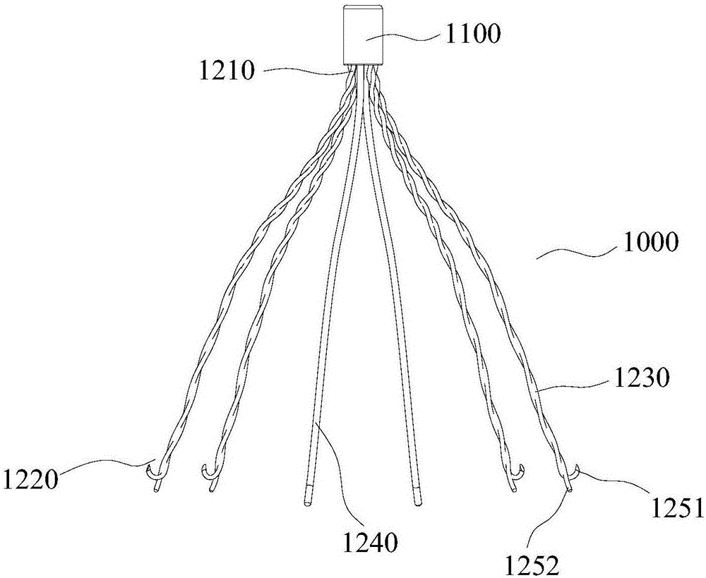
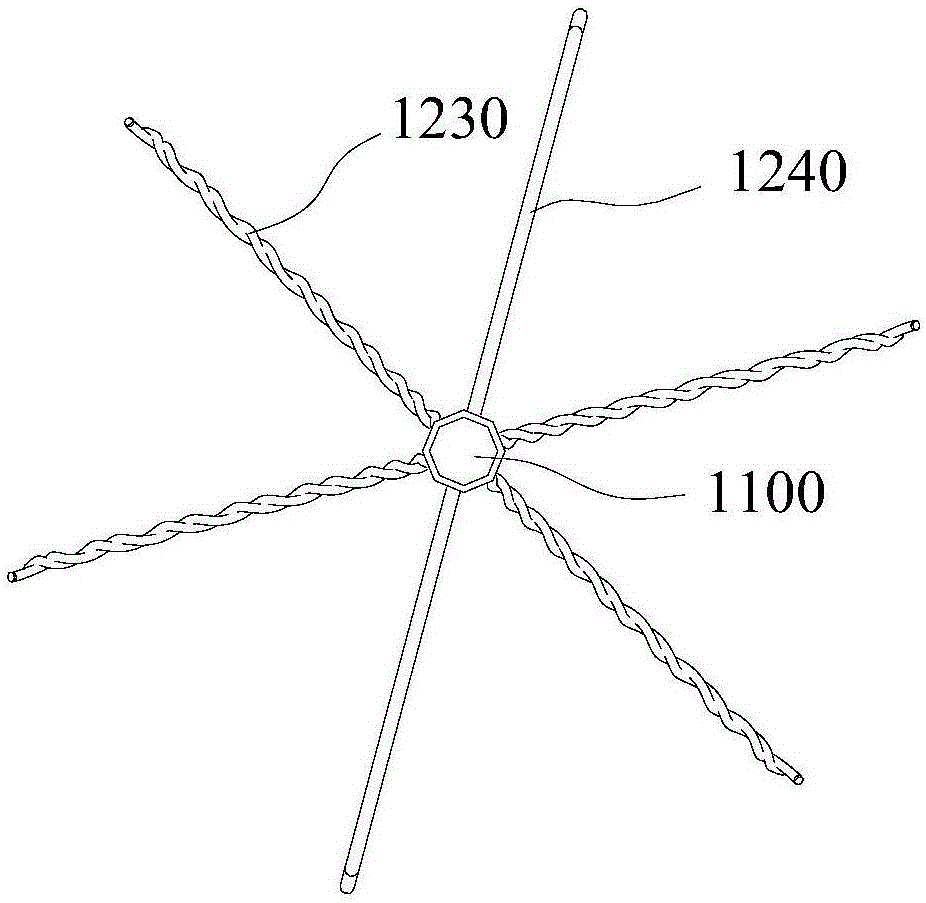
[0072] Such as Figure 1a , Figure 1b As shown, the vena cava filter 1000 of this embodiment includes a plurality of struts, one end of the plurality of struts is gathered and restrained in a 2.0mm sleeve 1100, and is fixed by argon arc welding to form a gathered end 1210, and the ends of the plurality of struts are The other end radiates to form a diverging end 1220 in the released state.

[0073] In the released state, a plurality of struts are roughly distributed on the same conical surface, and the diameter of the circle surrounded by each strut at the divergent end 1220 is the largest. The length of each strut is 30-70 mm, and the maximum diameter of the circle surrounded by the diverging ends 1220 is about 20-80 mm.

[0074] The number of poles is usually 4 to 18. In this embodiment, the number of poles is 6, of which 4 poles are twisted poles 1230, and 2 poles are non-twisted poles 1240. In the released state, The two non-twisted struts 1240 and the central axis of t...

Embodiment 2

[0087] Such as Figure 2a , Figure 2b As shown, the difference between this embodiment and Embodiment 1 is that the wire diameters of the twisting struts 2230 are different. The twisting rod 2230 is formed by twisting two metal wires with different diameters, wherein the wire 2261 with a thicker diameter does not twist, and the wire 2262 with a thinner diameter is wound around the wire 2261 with a thicker diameter. , and the winding pitch of the converging end 2210 is smaller than that of the diverging end 2220 .

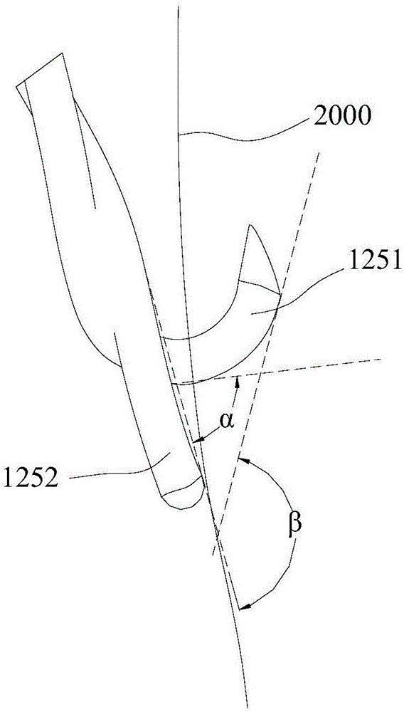
[0088] Such as Figure 2b , at the diverging end 2220 of the twisting pole 2230, the metal wire 2261 with a thicker wire diameter maintains the original extension direction, and the end of the metal wire 2262 with a smaller wire diameter bends toward the gathering end 2210 to form an anchor hook 2251.

[0089] The release process of this embodiment is the same as that of Embodiment 1.

Embodiment 3

[0091] Such as Figure 3a , Figure 3b As shown, the difference between this embodiment and Embodiment 1 is that the twisting strut is formed by intertwining three metal wires, the diameters of the three metal wires are the same, and the twist gradually decreases from the converging end 3210 to the diverging end 3220 . One metal wire of the twisted strut is bent near the divergent end 3220 to form an anchor hook 3251 , and the other two metal wires are side by side near the divergent end 3220 to maintain the original extension direction.

[0092] The release process of this embodiment is the same as that of Embodiment 1.


PUM


Abstract

The invention discloses a vena cava filter. The vena cava filter comprises a plurality of support rods, wherein one end of each of the support rods is gathered, and the other end of each of the support rods is radially dispersed under a releasing state; at least one part of the support rods are twisting support rods which are respectively formed by twisting a plurality of metal wires; each twisting support rod is formed by twisting two or more metal wires; the diameters of the metal wires on the same twisting support rod are the same or are different; at least one metal wire of each twisting support rod is bent at a part close to the radial end to form an anchor hook. The vena cava filter has the advantages that the strength is higher, the compliance is better, the releasing and recycling process is smooth, and the falling and dislocation risks are avoided.

Description

technical field [0001] The invention relates to the field of medical devices, in particular to a vena cava filter. Background technique [0002] Pulmonary embolism (PE) is a common health problem and the leading cause of death in all age groups. Most pulmonary embolisms are caused by deep vein thrombosis (DVT) in the lower extremities or in the pelvis. A blood clot that forms somewhere in the body may migrate through a vein back to the heart and into the lungs. Part of the blood and oxygen supply is cut off, resulting in pulmonary infarction. [0003] According to statistics, the mortality rate of untreated pulmonary embolism is 20%-30%, and the annual new cases account for about 0.2% of the total population. The vena cava filter has been proven to reduce the incidence of pulmonary embolism clinically. The filter is divided into permanent implantation filter and temporary filter. When the filter is implanted in the body, if the implantation position is improper or the filt...

Claims


Application Information

Patent Timeline
Patent Type & Authority Applications(China)
IPC IPC(8): A61F2/01
CPCA61F2/01A61F2002/016
Inventor 张庭超王永胜李阳
Owner HANGZHOU WEIQIANG MEDICAL TECH CO LTD
Why Eureka
Try Eureka