Electric valve

An electric valve and valve core technology, which is applied to lift valves, balance valves, valve devices, etc., can solve the problems of noise, processing and assembly errors, partial wear of the valve seat portion 72b, etc., and achieve the effect of reducing costs.

Inactive Publication Date: 2008-10-29
FUJIKOKI MFG CO LTD
View PDF2 Cites 28 Cited by
  • Summary
  • Abstract
  • Description
  • Claims
  • Application Information

AI Technical Summary

Problems solved by technology

[0007] However, in the above electric valve 10' and the electric valve described in the above Patent Document 1, the valve chamber forming member 74 constituting the valve body 70 is a press-formed part, and although the production cost is lower than that of a cutting part, the dimensional accuracy is slightly inferior. Since the valve seat part 72 as a cutting part and the guide part (guide sleeve 80) as a stamped part are installed on the valve chamber forming part 74, the processing and assembly errors and unevenness of each part cause the above-mentioned valve core 61 (the center line) is misaligned (axis misaligned) or inclined with respect to the valve seat portion 72b formed on the valve seat member 72 and the valve port 72a (the center line O)
Once such dislocation or inclination occurs, the following problems will occur: partial wear of the valve seat portion 72b; valve leakage in the closed state; noise caused by unwanted valve vibration; uneven flow rate; Action etc.
[0008] In addition, in the electric valve described in the above-mentioned Patent Document 2, the valve seat member and the guide member are composed of an integral part, but the valve chamber forming member is manufactured by cutting, and there is a problem in terms of cost.

Method used


Image

  • Electric valve
  • Electric valve

Examples


Embodiment Construction

[0018] Hereinafter, embodiments of the electric valve according to the present invention will be described with reference to the drawings.

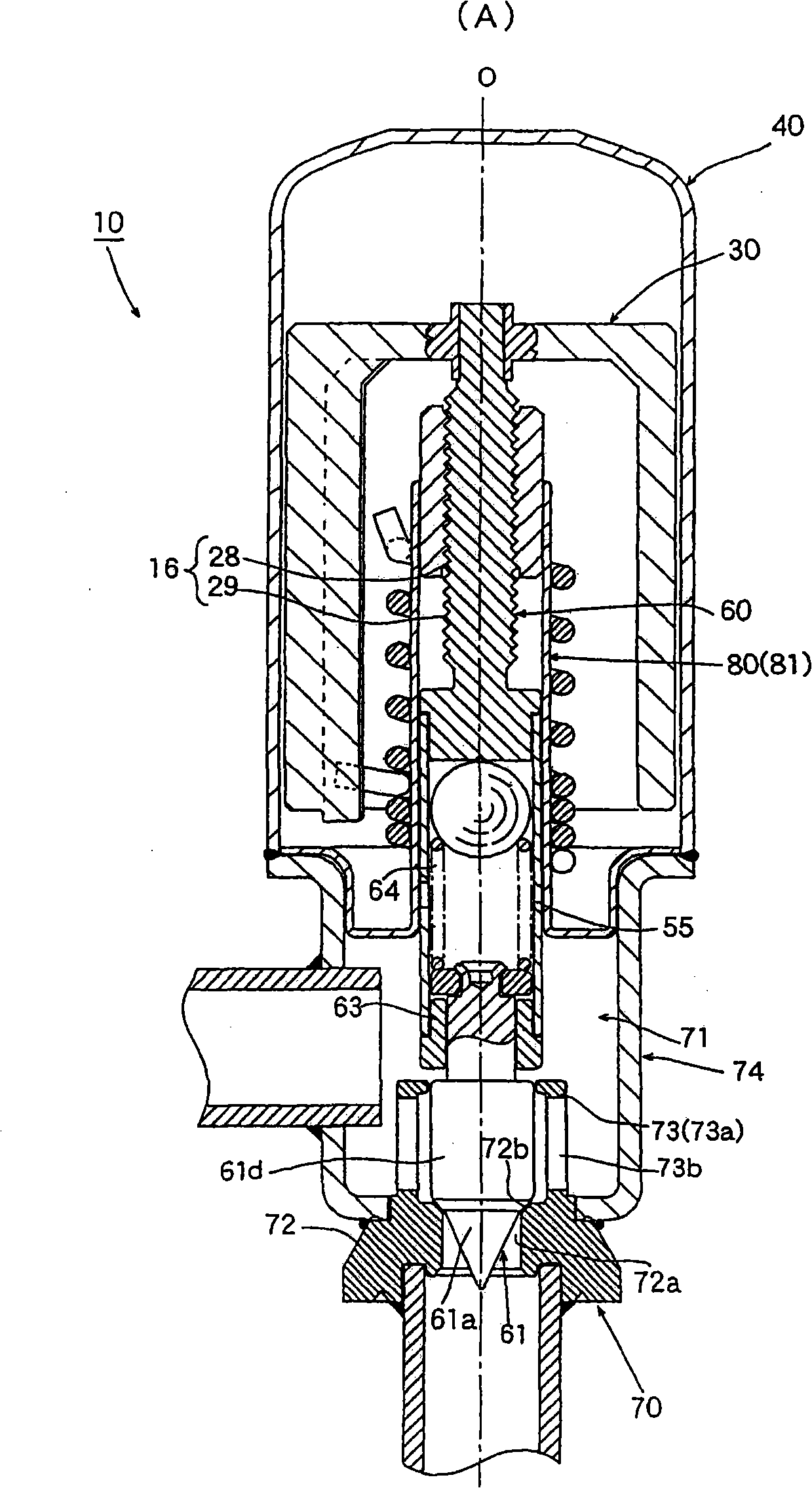
[0019] figure 1 It is a figure which shows one embodiment of the electric valve of this invention.

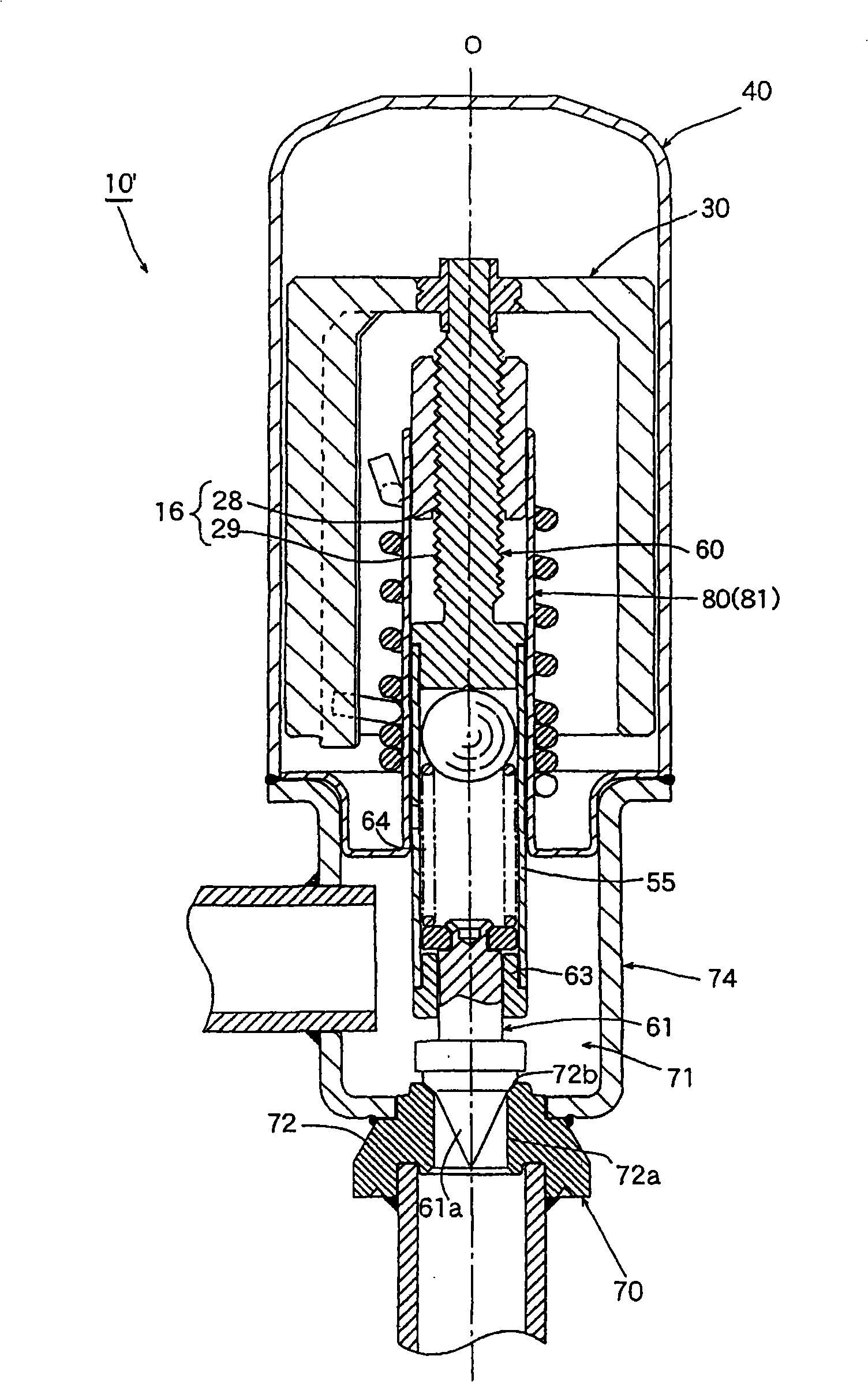
[0020] figure 1 The parts other than the valve body 70 and the spool 61 of the electric valve 10 shown are the same as those mentioned above figure 2 The electric valve 10' shown has substantially the same structure. Here, the same structure and the same functional parts are marked with common symbols and repeated descriptions are omitted. The following description focuses on the differences.

[0021] figure 1 In the electric valve 10 shown, the valve body 70 includes: a valve chamber forming part 74, which is made of a stamped part and forms a valve chamber 71 for fluid to flow in and out; a valve seat part 72, which is made of a cutting part and has a The valve seat portion 72b is in contact with and separated from the valve body ...


PUM


Abstract

The invention provides an electrically operated valve, which uses a valve chamber forming component of the press forming piece to reduce cost, and the valve core does not misplace and incline relatively to the valve seat, thus not resulting in eccentric abrasion of the valve seat, valve leakage under closing valve state, undesirable valve vibration and noise, flow rate unevenness and sliding resistance increase, etc. The electrically operated valve includes: a shell (40); a rotor (30) configured on the internal circumference of the shell (40); a valve shaft (60) connected and fixed on the rotor (30); a valve core (61) arranged at the lower end of the valve shaft (60); a guide sleeve (80) configured in the shell (40) for guiding the lift of the valve shaft (60) and the valve core (61); a valve body (70), including a valve chamber forming component (74) and a valve seat component (72), wherein the valve chamber forming component is composed of a press forming piece and forms a valve chamber (71) for the fluid flowing in and out, while the valve seat component is composed of a cutting processing piece and provided with a valve seat part (72b) contacted with and separated from the valve core (61); and a thread feeding mechanism (16), resulting in contact and separation of the valve core (61) and the valve seat part (72b) by following the rotation of the rotor (30), the guiding part (73) for guiding the lift of the valve core (61) forms a whole with the valve seat component (72) through cutting processing.

Description

technical field [0001] The present invention relates to a stepping motor-driven electric valve incorporated in a refrigeration cycle such as an air conditioner or a refrigerator as a flow control valve. Background technique [0002] As electric valves used in air conditioners, refrigerators, etc., for example, known figure 2 structure shown. The stepping motor-driven electric valve 10' of the illustrated example includes: a casing 40; a guide sleeve 80 having a cylindrical portion disposed in the casing 40; a rotor 30 disposed on the inner periphery of the casing 40; connected and fixed on The valve shaft 60 (rotor shaft) on the rotor 30; the cylindrical valve frame 55 arranged at the lower end of the valve shaft 60 and inserted into the cylindrical portion 81 of the guide sleeve 80; the valve core 61, which The upper part is inserted into the valve frame 55, and can move and rotate relatively in the axial direction relative to the valve shaft 60, and the valve core 61 is ...

Claims


Application Information

Patent Timeline
Patent Type & Authority Applications(China)
IPC IPC(8): F16K31/04F16K1/38F16K17/36F25B41/00
Inventor 菅沼威
Owner FUJIKOKI MFG CO LTD
Why Eureka
Try Eureka