Pressing and rotating mechanism for gasket on cosmetic bottle body

A technology of gasket pressing and rotating mechanism, used in screw caps, liquid handling, bottle filling, etc., can solve the problems of affecting normal rotation, low efficiency, poor effect, etc., and achieve the effect of ensuring normal rotation

Inactive Publication Date: 2020-06-12
佛山艾嘉化妆品有限公司
View PDF0 Cites 7 Cited by
  • Summary
  • Abstract
  • Description
  • Claims
  • Application Information

AI Technical Summary

Problems solved by technology

[0002] The existing cosmetic bottle body needs to place a sealing gasket before installing the bottle cap to prevent the liquid in it from flowing out. However, the existing method is to manually place the sealing gasket and then press it manually, which has low efficiency and poor effect, and the existing The bottle body is generally placed on the rotating disk, and rotated to the front of the operator through the rotating disk, the operator then places the gasket and presses it tightly. When it presses down on the bottle body, the edge of the rotating disk will be pressed and tilted. affect its normal rotation

Method used


Image

  • Pressing and rotating mechanism for gasket on cosmetic bottle body
  • Pressing and rotating mechanism for gasket on cosmetic bottle body
  • Pressing and rotating mechanism for gasket on cosmetic bottle body

Examples


Embodiment

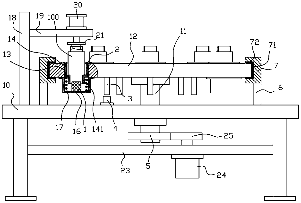
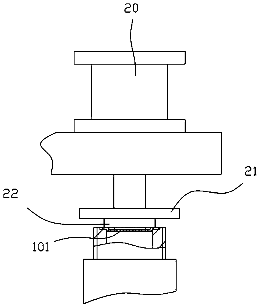
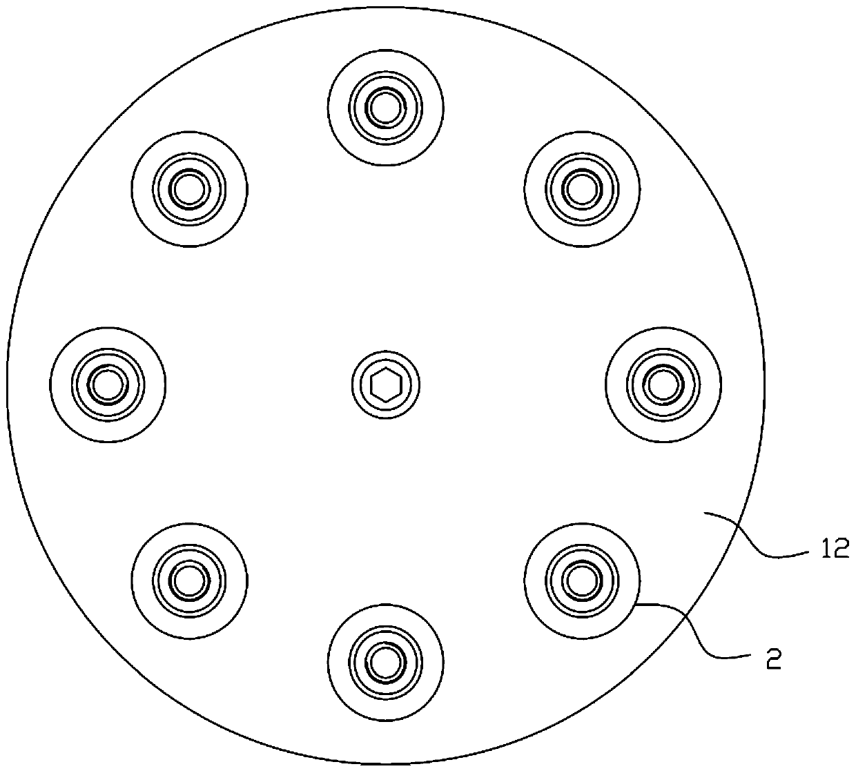
[0019] Example: see Figure 1 to Figure 3 As shown, a gasket compression rotation mechanism on a cosmetic bottle includes a frame 10, the middle part of the top plate of the frame 10 is hinged with a vertical main shaft 11, and the bottom end of the vertical main shaft 11 extends out of the top plate of the frame 10 The top of the vertical spindle 11 protrudes from the top of the top plate of the frame 10 and is fixed with a rotating disk 12. The edge of the rotating disk 12 is formed with a plurality of vertical through holes 13, and the guide sleeve 14 is inserted in the vertical In the through hole 13, the outer side wall of the guide sleeve 14 is close to the inner side wall of the vertical through hole 13, and the lower support sleeve 16 is fixed on the bottom surface of the edge portion of the rotating disk 12, and the lower support sleeve 16 is positioned at the front of the vertical through hole 13. Below, the top surface of the bottom plate of the lower supporting sle...


PUM


Abstract

The invention discloses a pressing and rotating mechanism for a gasket on a cosmetic bottle body. The pressing and rotating mechanism comprises a rack, wherein a vertical main shaft is hinged to the middle of a top plate of the rack; the bottom end of the vertical main shaft extends out of the bottom surface of the top plate of the rack, and the top of the vertical main shaft extends out of the top surface of the top plate of the rack to be fixedly connected with a rotating disc; a plurality of vertical through holes are formed in the edge part of the rotating disc; guide sleeves are insertedin the vertical through holes in a sleeved mode the outer side walls of the guide sleeves are tightly attached to the inner side walls of the vertical through holes; and a lower supporting sleeve is fixed to the bottom surface of the edge part of the rotating disc, the lower supporting sleeve is positioned under the vertical through holes, and buffer springs are fixed to the top surface of a bottom plate of the lower supporting sleeve. According to the pressing and rotating mechanism, the gasket placed on a bottle mouth of the bottle body can be pressed automatically, and a buffer mechanism arranged on the pressing and rotating mechanism can ensure that the bottle body is not subjected to hard impact when the gasket is pressed down; and meanwhile, clamping blocks arranged on the pressing and rotating mechanism can ensure that the edge part of the rotating disc has supporting force when the rotating disc is pressed, so that the rotating disc rotates normally without tilting.

Description

technical field [0001] The invention relates to the technical field of cosmetic equipment, in particular to a gasket pressing and rotating mechanism on a cosmetic bottle body. Background technique [0002] The existing cosmetic bottle body needs to place a sealing gasket before installing the bottle cap to prevent the liquid in it from flowing out. However, the existing method is to manually place the sealing gasket and then press it manually, which has low efficiency and poor effect, and the existing The bottle body is generally placed on the rotating disk, and rotated to the front of the operator through the rotating disk, the operator then places the gasket and presses it tightly. When it presses down on the bottle body, the edge of the rotating disk will be pressed and tilted. affect its normal rotation. Contents of the invention [0003] The purpose of the present invention is to address the deficiencies of the prior art, and to provide a gasket pressing and rotating...

Claims


Application Information

Patent Timeline
Patent Type & Authority Applications(China)
IPC IPC(8): B67B5/03B67B3/20
CPCB67B3/2013B67B5/034
Inventor 苏志远
Owner 佛山艾嘉化妆品有限公司
Why Eureka
Try Eureka