Magnetic head

A technology of magnetic head and shielding shell, which is applied in the field of magnetic head for data piracy

Inactive Publication Date: 2008-10-29
太克莱克株式会社
View PDF1 Cites 9 Cited by
  • Summary
  • Abstract
  • Description
  • Claims
  • Application Information

AI Technical Summary

Problems solved by technology

Of course, such beh

Method used


Image

  • Magnetic head
  • Magnetic head
  • Magnetic head

Examples


Embodiment 1

[0049] Hereinafter, embodiments of the present invention will be described with reference to the drawings.

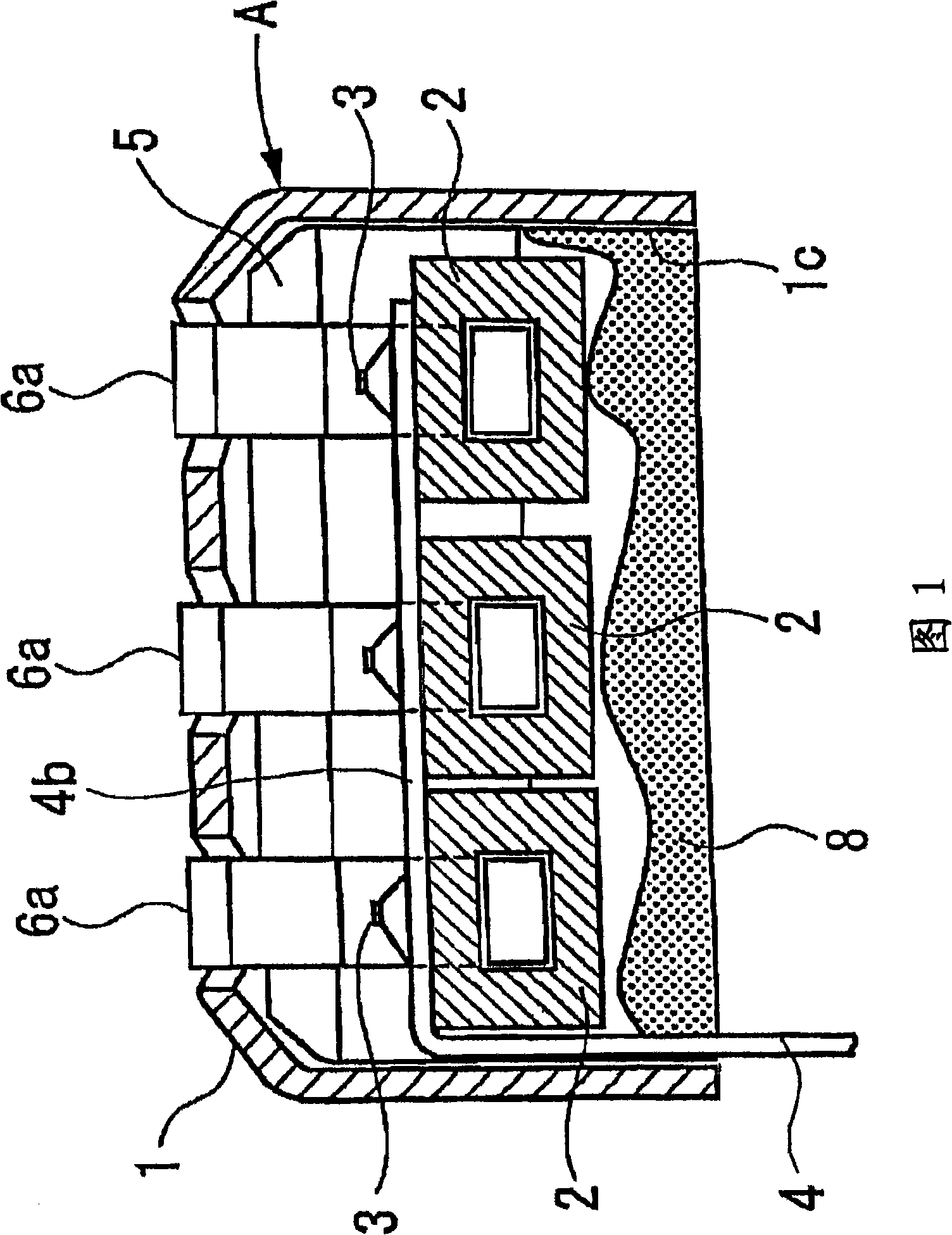
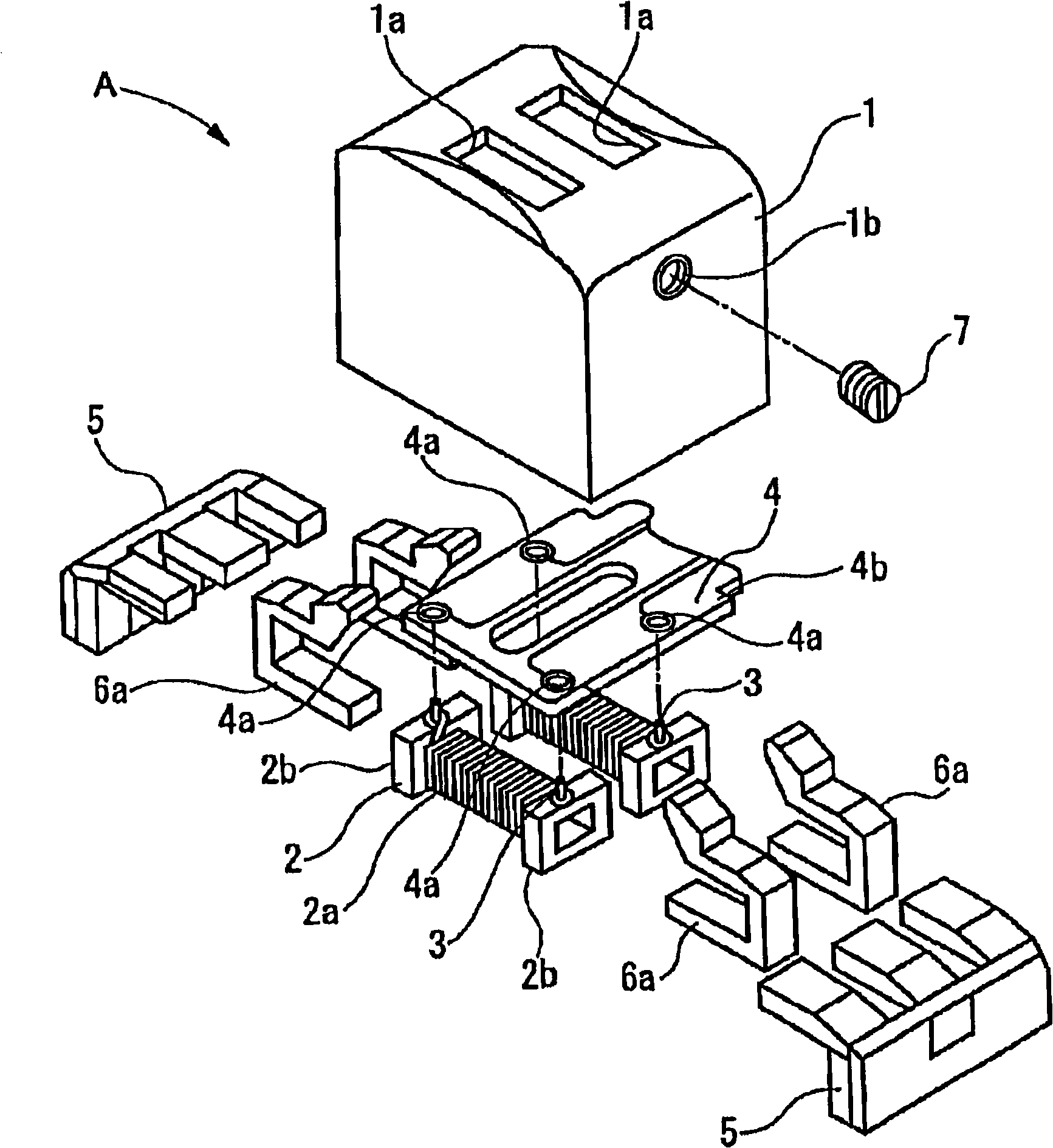
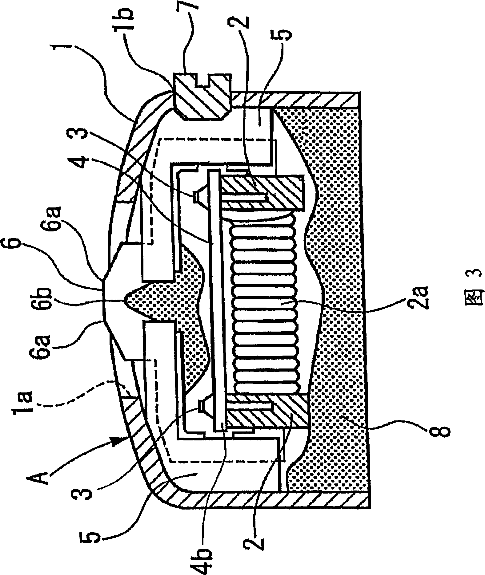
[0050] Fig. 1 is a side sectional view of a magnetic head of the present invention. figure 2 It is an exploded perspective view showing the structure of the magnetic head of the present invention. Fig. 3 is a front sectional view of the magnetic head of the present invention.

[0051] Figure 1, figure 2 And as shown in FIG. 3 , in the magnetic head A of the embodiment of the present invention, in the shield case 1 having a substantially rectangular parallelepiped shape and opening below, a plurality of bobbins 2 around which electric wires 2 a are wound are arranged side by side laterally. The upper surfaces of the flange portions 2b at both ends of 2 are respectively provided with lead pins 3 as terminals for external connection (in Fig. 1 and figure 2 The number of wire racks 2 configured in different). A flexible circuit board 4 is used as the signal line, corres...


PUM


Abstract

A magnetic head of a credit card identification terminal for reading card data which can prevent card data from being illegally acquired. The magnetic head includes a generally box-shaped sealed case having an open side; a bobbin with an electric wire wound thereon provided in the sealed case; a core member extending from the bobbin and having an end protruding to the outside of the sealed case through a through-hole formed through a side of the sealed case opposite the opening; a terminal pin connected to the wire wound on the bobbin; and resin filled in the hollow space in the sealed case, the terminal pin is embedded in the resin filled in the sealed case, one end of a flexible wiring substrate is connected to the terminal pin, and the other end of the flexible wiring substrate extends to the outside of the sealed case from the opening.

Description

technical field [0001] The present invention relates to a magnetic head that uses a magnetic card as a data recording medium for reading signals in a card reader, etc., and particularly relates to a magnetic head that can prevent data on the card from being stolen by an illegal method. Background technique [0002] In recent years, due to the popularization of the credit card constituted by the above-mentioned magnetic card, settlements using the credit card when purchasing goods frequently occur. Specifically, the credit card is inserted into the card insertion port of the credit card authentication terminal located in each store, and the card data on the customer's credit card is read by the card reader installed in the credit card authentication terminal. After that, the owner of the credit card Enter the password, and proceed to settlement after verification and personal confirmation. [0003] In such a credit card authentication terminal, a magnetic head B as shown in ...

Claims


Application Information

Patent Timeline
IPC IPC(8): G11B5/187G11B5/255
Inventor 堀口昌男大坂稔
Owner 太克莱克株式会社
Why Eureka
Try Eureka