Vibration type convey

A conveying device, a vibrating technology, applied in the direction of vibrating conveyors, conveyors, conveyor objects, etc., can solve the problems of adjusting vibration characteristics, damage, piezoelectric body of the vibration body, etc., to improve stability and durability, Improve transmission efficiency and reduce the effect of violent movement

Active Publication Date: 2008-11-05
DAISHIN CO LTD
View PDF9 Cites 12 Cited by
  • Summary
  • Abstract
  • Description
  • Claims
  • Application Information

AI Technical Summary

Problems solved by technology

[0014] However, in each of the above-mentioned devices, the conveying body is connected to the inertial body (weight) through the vibrating body, and is also connected to the base through the elastic support body. Therefore, there is a problem that the transfer of vibration energy from the conveying body to the The flow of the base (the above-mentioned patent documents 1, 2 and 4); or although the outflow of vibration energy to the installation surface can be reduced, it is necessary to use a device with a special structure and shape as the vibration body or support structure, so the manufacturing cost increases , and it is difficult to adjust the vibration characteristics with respect to the conveyed object, etc., and flexibly respond according to the situation or environment (the above-mentioned patent documents 3 and 4); Therefore, the situation is basically the same as that of the existing rubber or spring setting the base on the installation surface, and the outflow of vibration energy mainly depends on the elastic support between the inertial body and the base. elastic properties, therefore, the vibration energy transmitted to the installation surface cannot be sufficiently reduced (the above-mentioned patent documents 5, 6, 7, 8 and 9)
[0015] And, for example, in the above-mentioned Patent Document 3, a structure in which each conveying body is respectively connected via an elastic support body on one vibration part of a Y-shaped vibrating body and the other side vibration part, in such a plurality of conveying bodies In the connecting structure connected to the vibrating body, since the load on the vibrating body increases, the vibrating body, such as the piezoelectric body, may be damaged such as broken

Method used


Image

  • Vibration type convey
  • Vibration type convey
  • Vibration type convey

Examples


Embodiment Construction

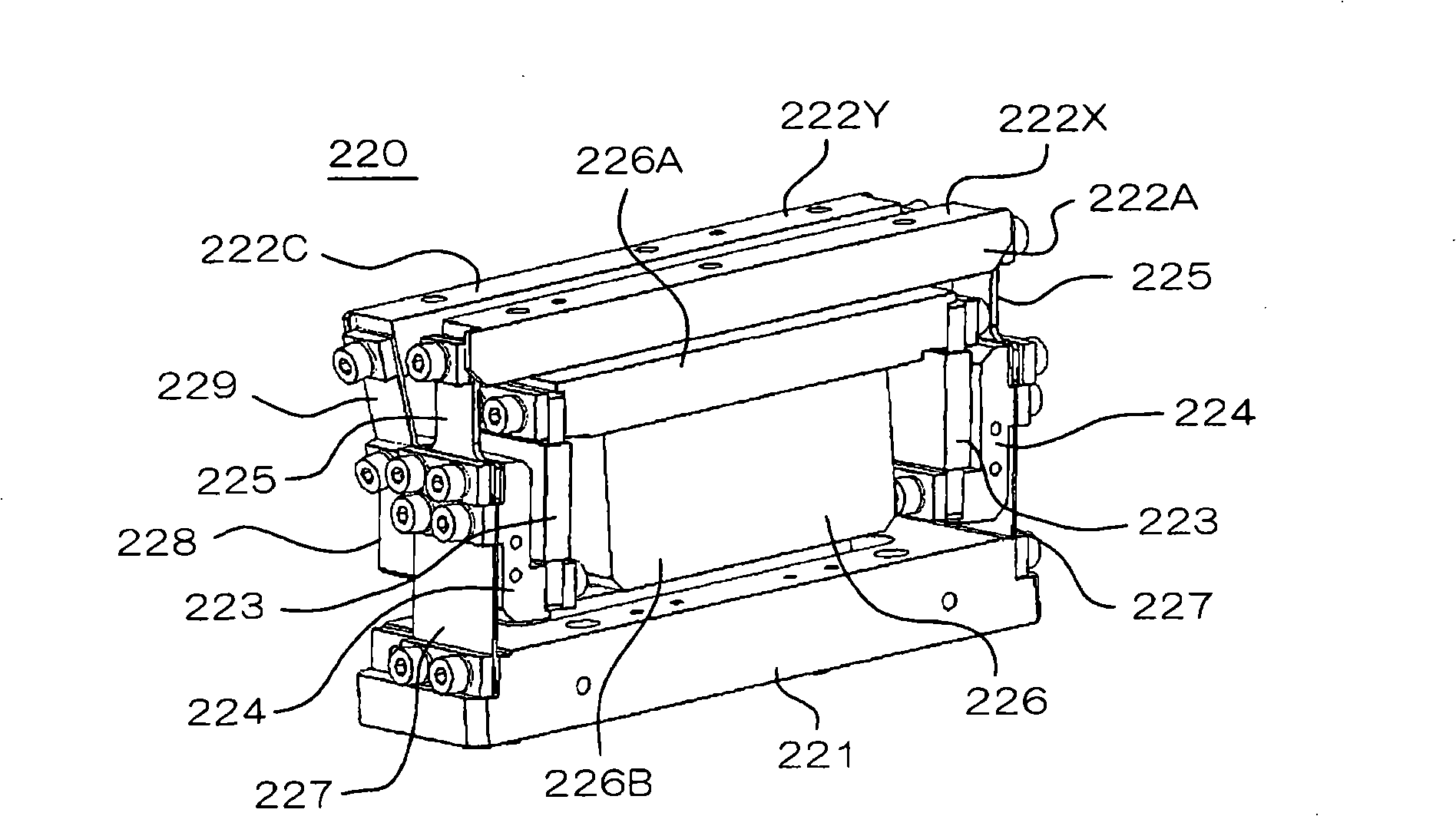
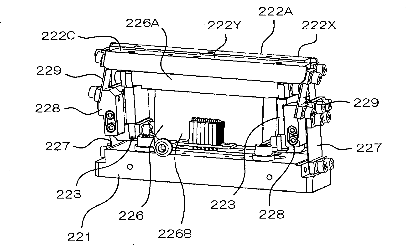
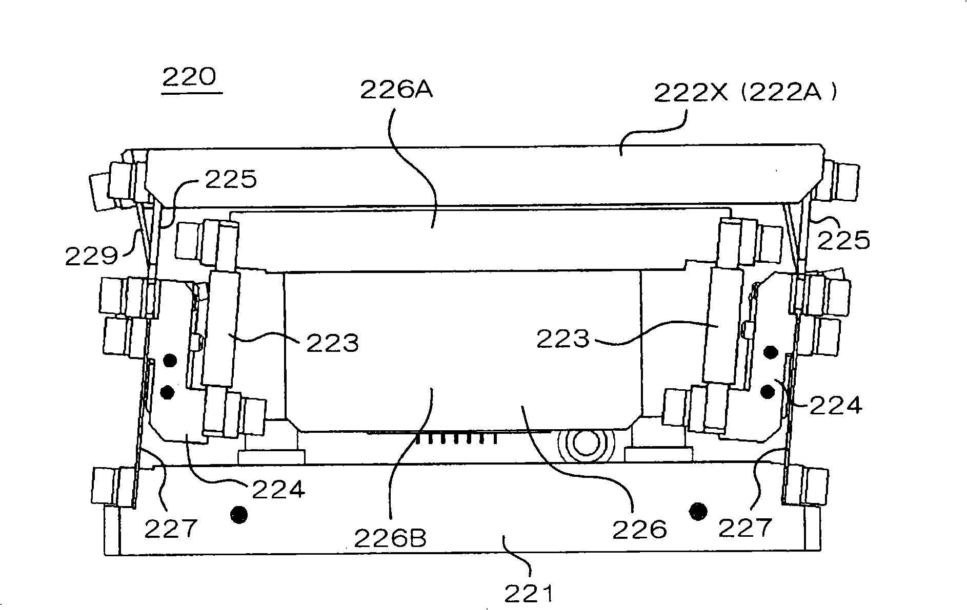
[0031] Embodiments of the present invention will be described below together with illustrated examples. figure 1 It is a schematic front side perspective view of the vibrating conveying device 220 according to this embodiment in a state where the conveying block 221B serving as a constituent part of the first conveying body and the conveying block 222B serving as a constituent part of the second conveying body are removed, figure 2 It is the rear side perspective view, image 3 is the front view, Figure 4 is the rear view, Figure 5 is the right side view, Image 6 It is a schematic plan view of a configuration example of a vibrating conveyor.

[0032] The vibratory conveying device 220 of the present embodiment has a base 221 and a first conveying body 222X (refer to Image 6 . Depend on figure 1 with figure 2 shown in slot 222A and Image 6shown conveying block 222B), the vibrating body 223 for vibrating the first conveying body 222X, the connecting member 224 con...


PUM


Abstract

A vibratory conveying apparatus including: a base; a first conveying body arranged above the base; a vibrating body for vibrating the first conveying body; a first elastic support connected between the first conveying body and one side of the vibrating body; an inertia body which is connected to the other sides of the vibrating body and constitutes a free end of vibration; and a second elastic support connected between the base and the one side of the vibrating body, and the first elastic support, and further including: a second conveying body; and a third elastic support connected between the second conveying body and the one side of the vibrating body, the first elastic support, and the second elastic support.

Description

technical field [0001] The present invention relates to a vibrating conveying device, and particularly relates to a vibrating conveying device suitable for conveying a large amount of small electronic components. Background technique [0002] Generally, various vibrating conveyors are used in factories to convey small parts such as electronic components. In recent years, such vibrating conveying devices have been required to have high feeding speed and feeding accuracy, and high speed and high performance are urgently needed. Furthermore, since a mounting device requiring high precision and other processing devices are installed at the supply place of the above-mentioned electronic components, there is a problem that the vibration of the vibrating conveying device affects the operation of the processing device. Therefore, various proposals have been made so far to prevent the vibration generated by the vibrating conveyor from being transmitted to the outside as much as poss...

Claims


Application Information

Patent Timeline
Patent Type & Authority Applications(China)
IPC IPC(8): B65G27/08B65G27/24
CPCB65G27/08B65G27/10B65G27/16B65G47/14
Inventor 三村太郎原順一山田泰
Owner DAISHIN CO LTD
Why Eureka
Try Eureka