
Connecting rod for drawing system and loom comprising such a connecting rod

A technology for connecting rods and looms, applied in the field of connecting rods, can solve the problems of increasing the cost of shedding forming devices, etc.

Active Publication Date: 2008-11-05
STAUBLI FAVERGES SA
View PDF0 Cites 1 Cited by
  • Summary
  • Abstract
  • Description
  • Claims
  • Application Information

AI Technical Summary

Problems solved by technology

The lateral dimensions of the individual stabilizers are also limited by the separation distance
Such a stabilizing device increases the cost of installing and maintaining the shedding device of the loom

Method used


Image

  • Connecting rod for drawing system and loom comprising such a connecting rod
  • Connecting rod for drawing system and loom comprising such a connecting rod
  • Connecting rod for drawing system and loom comprising such a connecting rod

Examples


Embodiment Construction

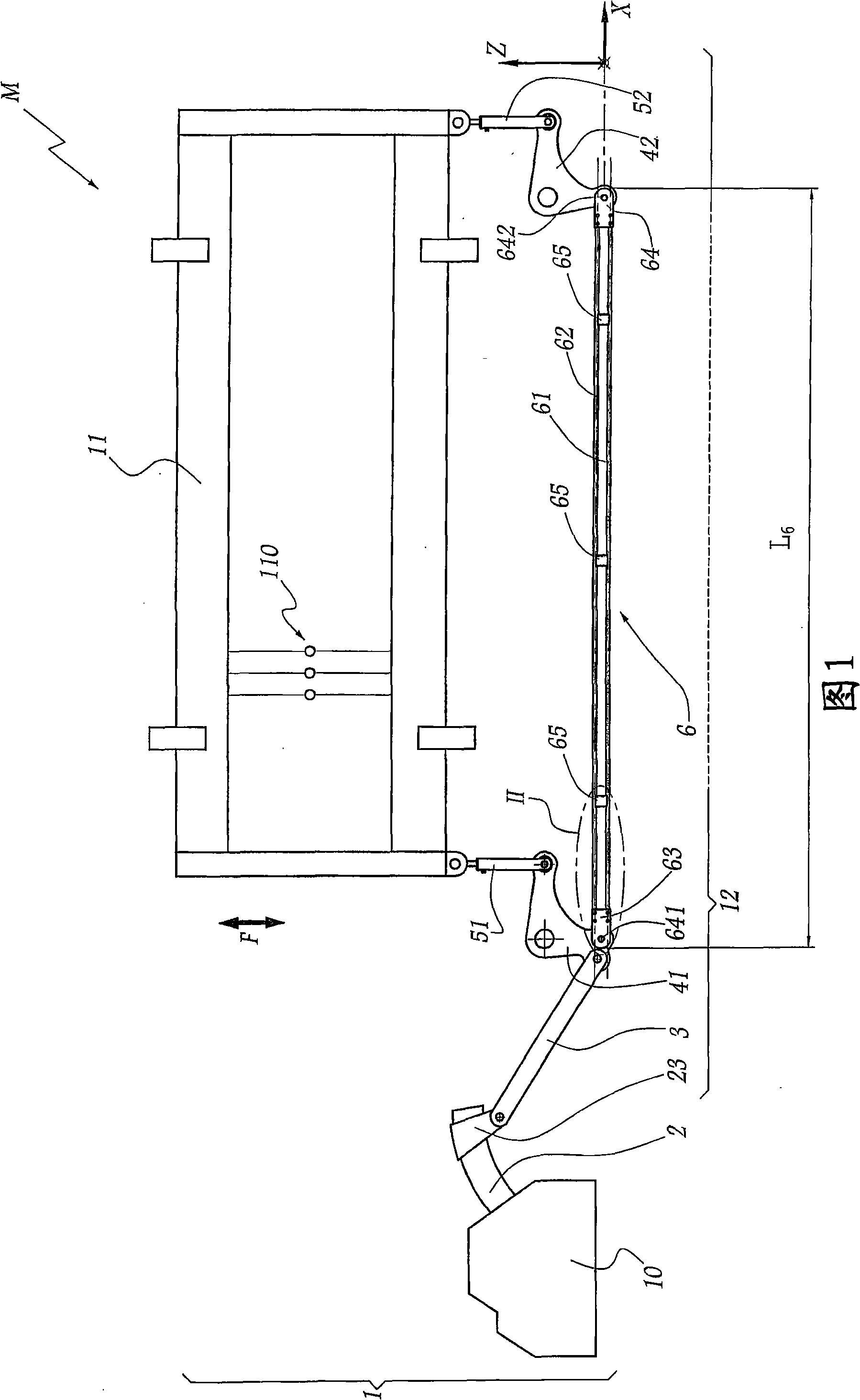
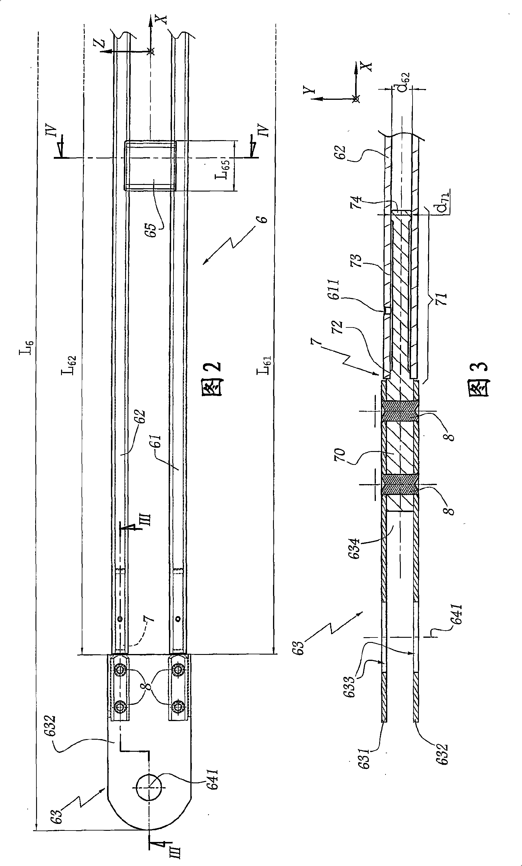
[0036] FIG. 1 shows a weaving machine M provided with a shedding device 1 comprising several heald frames, one of which is indicated at 11 in the figure. In a manner known per se, the heald frame 11 is equipped with a heald 110 , each eyelet of which is passed by a warp thread perpendicular to the plane of the heald frame 11 , ie the plane of FIG. 1 .

[0037] Each heald frame 11 is forced to move in the direction indicated by the double arrow F so as to oscillate vertically parallel to an axis. This motion is imparted by the dobby 10 . This movement is transmitted from the dobby 10 to the heald frame 11 by a series of connecting rods, levers and hooks forming the drafting system 12 .

[0038] The drafting system 12 is actuated by the output lever 2 of the dobby. The output lever 2 comprises a hook 23 placed on the output lever 2 and hinged to the first connecting rod 3 . The first connecting rod 3 in turn drives the left side oscillating lever 41 which drives the left side...


PUM


Abstract

A connecting rod (6) used in a drawing system (12) of a loom extends along a longitudinal direction (X), which comprises at least two overlapped main rods (61, 62), extending approximately along the longitudinal direction (X), and at least a spacer arranged between the main rods (61, 62), wherein the spacer or each spacer (65) is away from each end part of the connecting rod.

Description

technical field [0001] The invention relates to a connecting rod for a drafting system of a weaving machine and a shedding device of a weaving machine having several drafting systems comprising at least one such connecting rod. Background technique [0002] A shedding device for a weaving machine generally comprises several juxtaposed heald frames actuated individually by a drafting system. This drafting system consists of a set of connecting rods and levers for each heald frame, which are installed in parallel in a limited space. The drafting system and the heald frames are juxtaposed in a lateral direction corresponding to the direction of the warp threads. [0003] The connecting rods and levers of each drafting system are designed to transmit to the heald frame the motion exerted by the shedding device, which may be a dobby, cam mechanism or actuator. Consequently, the connecting rods and levers are subjected to high and repeated forces. [0004] In particular, the co...

Claims


Application Information

Patent Timeline
IPC IPC(8): D03D49/00D03D51/02D03C13/00F16H51/00
CPCD03C1/16D03C9/0683
Inventor 安德烈·菲梅
Owner STAUBLI FAVERGES SA
Learn More