Electronic apparatus power supply output end structure

A technology for power output terminals and electronic appliances, applied in circuits, discharge lamps, discharge tubes, etc., can solve problems such as increasing product thickness, poor electrical conductivity, and shell deformation, and achieve the effect of reducing the possibility of deformation and reducing prestress.

Inactive Publication Date: 2008-11-05
卢润侨 +1
View PDF0 Cites 7 Cited by
  • Summary
  • Abstract
  • Description
  • Claims
  • Application Information

AI Technical Summary

Problems solved by technology

This kind of power output terminal structure has the following disadvantages: if the positive shrapnel on the side is pressed tightly, it will make it difficult to take out the battery; if the positive shrapnel on the side is pushed loosely, it may cause poor conduction; The thickness of the product is increased, and because the elastic force of the shrapnel forms a prestress in the shell, it may cause the shell of the product to deform

Method used


Image

  • Electronic apparatus power supply output end structure
  • Electronic apparatus power supply output end structure
  • Electronic apparatus power supply output end structure

Examples


Embodiment Construction

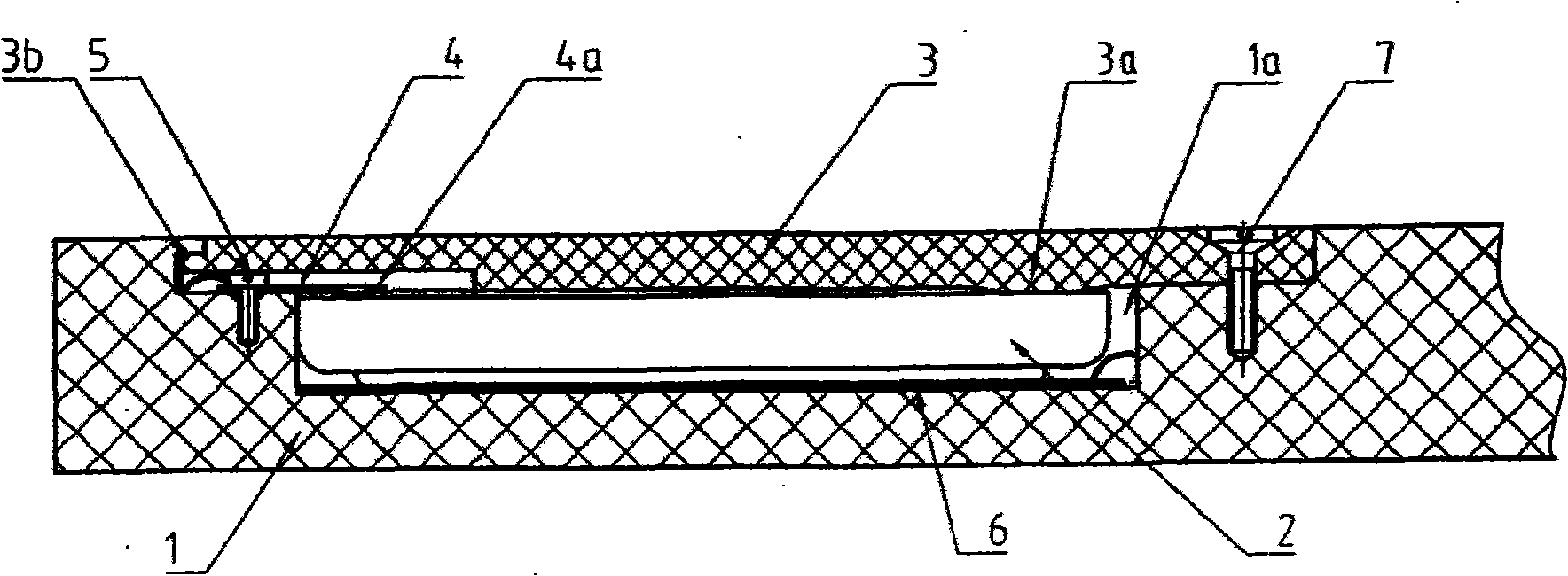
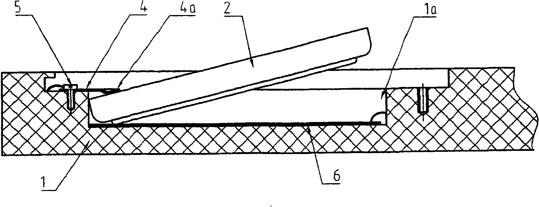
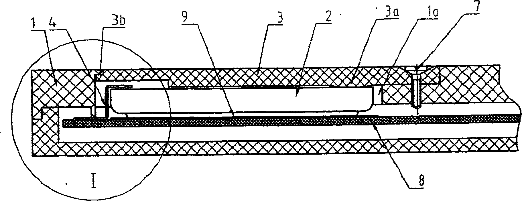
[0023] Embodiment 1 of the structure of the output end of the electronic appliance power supply of the present invention is as figure 1 and figure 2 As shown, it includes an electronic appliance housing 1, a PCB circuit board (not shown in the figure), and a button battery 2 as a power source. On the casing 1 there is a battery compartment 1a which accommodates the button battery 2 and opens outwards. The button battery 2 has two output terminals as a power supply, the first power supply output terminal is a metal shrapnel 4, one end of the metal shrapnel 4 is fixed on the shell 1 with a screw 5, and the other end 4a extends into the battery compartment and is pressed by its own elastic force. On the end face of the positive pole (outer pole) of the button battery 2, near the edge. The second power output terminal is the metal sheet 6 located at the bottom of the battery compartment 1a, and the metal sheet 6 is in contact with the negative pole (central pole) of the button ...


PUM


Abstract

The invention discloses a power output structure of the electronic apparatus, including an electronic apparatus case, a PCB circuit board, a button cell as the power, a first power output end and a second power output end. A battery storehouse with an open outwards is arranged on the case, wherein the outside of the battery storehouse is closed by the battery storehouse cover. The first power output end is a metal shrapnel, with one end fixed on the case or the PCB circuit board, and the other end pressed on the part near the battery edge of the epiboly extremeness of the button cell by the bounce of the metal shrapnel. The second power output end is contacted with the central pole of the button cell. The invention is a power output structure with convenient assemble and unassemble of the button cell and reliable conduction.

Description

[technical field] [0001] The invention relates to an electronic appliance, in particular to a power output terminal structure using a button battery as a power source in the electronic appliance. [Background technique] [0002] Many small and portable electronic appliances, such as electronic products such as pocket calculators, pedometers, and portable perpetual calendars, are small in size and low in power consumption, and button batteries are often used as the power supply for power supply. The two output poles of the button battery, one wrapped outside the battery, is usually the positive pole; the other is wrapped in the center of the battery, usually the negative pole. In order to load and unload the battery, there is a battery compartment opening outwards to accommodate the button battery on the housing of the electronic appliance, and the outside of the battery compartment is closed by a battery compartment cover. The two power output terminals of electronic applian...

Claims


Application Information

Patent Timeline
Patent Type & Authority Applications(China)
IPC IPC(8): H01R33/05H01R33/18H01R33/20H01R13/22
Inventor 芦雷
Owner 卢润侨
Why Eureka
Try Eureka