
Feeding mechanical arm of meter lathe

A technology for instrument lathes and manipulators, applied in the field of instrument lathe feeding and feeding manipulators, can solve problems such as difficulty in improving processing efficiency and quality, machine jamming, and difficult positioning, and achieves overcoming the problem of inertial force oscillations, accurate return positioning, and improving processing efficiency and processing quality effects

Inactive Publication Date: 2011-05-11
盛卫星
View PDF0 Cites 0 Cited by
  • Summary
  • Abstract
  • Description
  • Claims
  • Application Information

AI Technical Summary

Problems solved by technology

Although the structure of the device is simple, after many years of use, it has been found that because the return stroke of the entire device only depends on the restoring force of the return spring, there is an inertial force in the feeding part when it moves, making it difficult to position the feeding part to reach the limit position. Oscillations often occur when the initial position of the feed material is reached, especially when the return spring of the equipment is fatigued after a long time of operation, which makes the jamming phenomenon frequent in actual production. On the one hand, it will cause damage to parts, on the other hand It also makes it difficult to improve processing efficiency and quality

Method used


Image

  • Feeding mechanical arm of meter lathe
  • Feeding mechanical arm of meter lathe
  • Feeding mechanical arm of meter lathe

Examples


Embodiment Construction

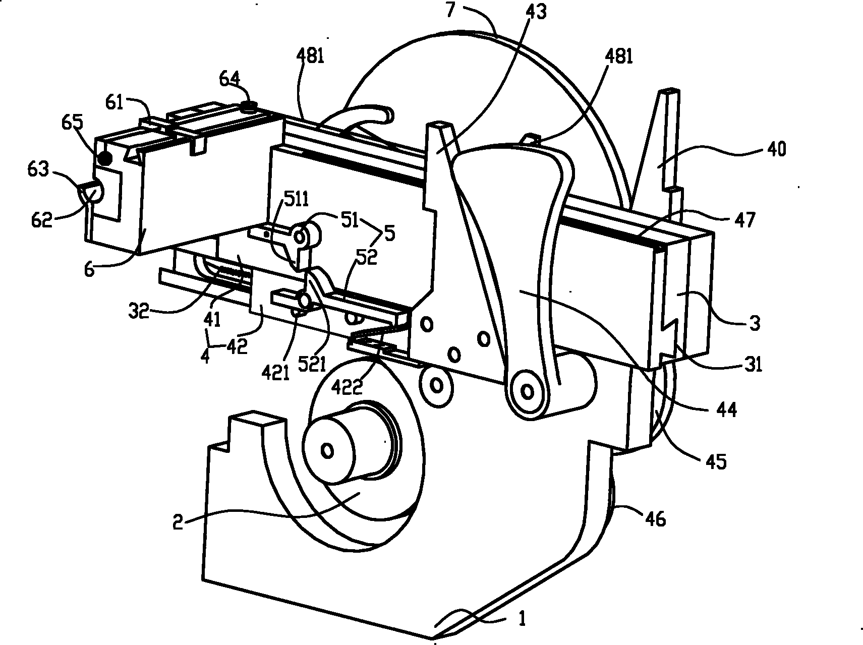
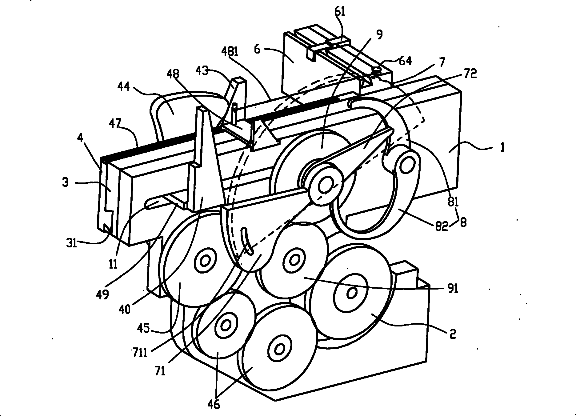
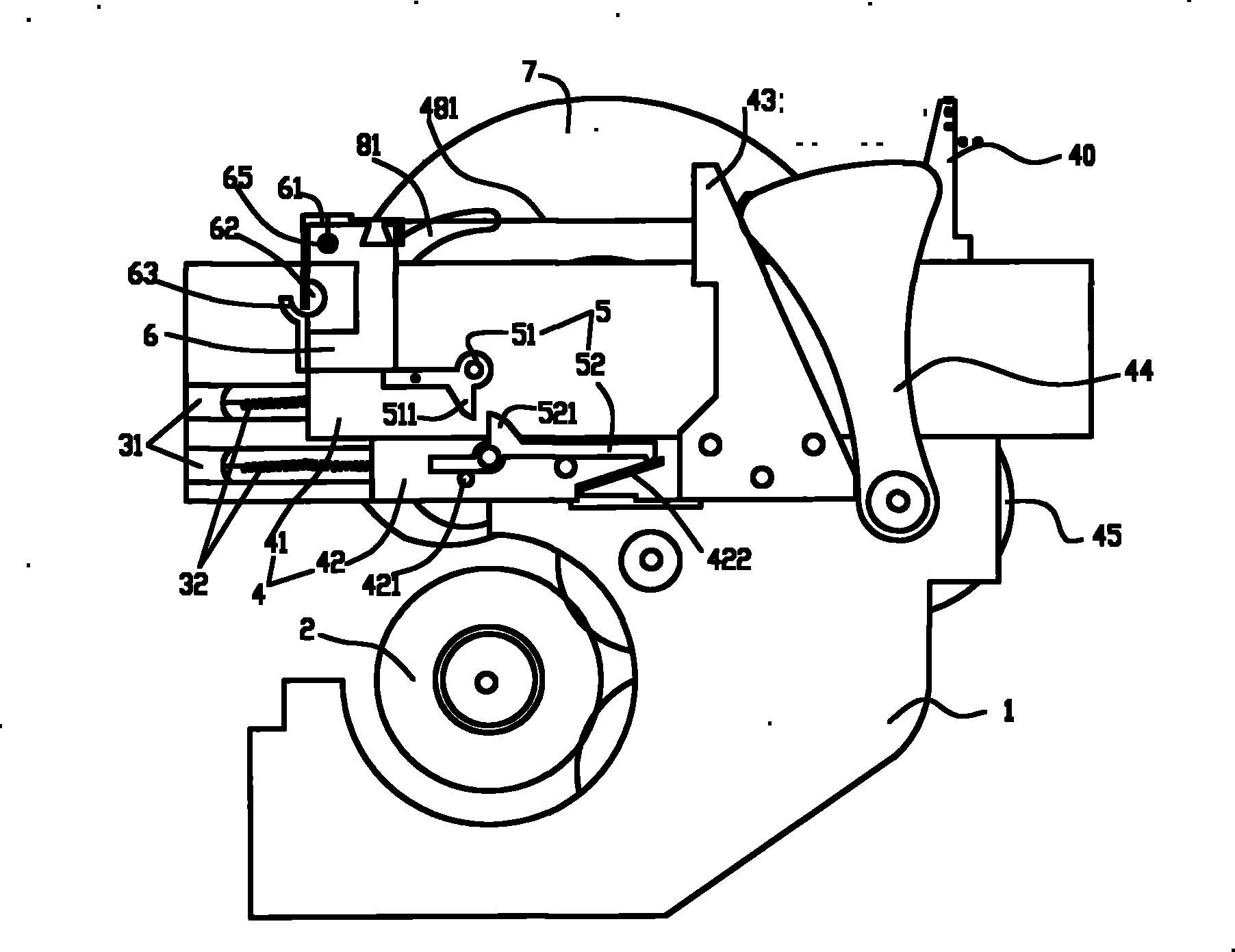
[0019] Such as figure 1 , 2 , 3 and 4, a feeding and feeding manipulator for an instrument lathe, including a bracket 1, a driving gear 2 is hollowed out in the middle of the bracket 1 for connecting an external motor, and a carriage 3 is fixedly installed on one side of the upper part of the bracket, while the upper part of the bracket The rear end is provided with an eccentric wheel 44 on the carriage side. A transverse through hole 11 is correspondingly provided on the mobilizer 3 and the bracket 1 , and a slider 4 that can slide along a dovetail groove 31 thereon is provided on the outer side of the moratorium 3 .

[0020] The sliding plate 4 is divided into an upper sliding plate 41 and a lower sliding plate 42, both of which are movably connected with the carriage 3 through a dovetail groove 31 and a return spring 32 respectively, and a linkage structure 5 is arranged at the joint of the two. The linkage structure 5 is composed of an upper slide plate part and a lower ...


PUM


Abstract

The invention discloses an instrument lathe feeding and conveying manipulator, comprising a bracket; the middle of the bracket is hollowly provided with a driving gear; one side at the upper part of the bracket is fixedly provided with a carriage provided with a sliding plate; the front end of the sliding plate is provided with a material inlet slideway; the tail of the sliding plate is provided with a feeding large-hump, and an inclined plane of the feeding large-hump faces backwards; the rear part of the feeding large-hump is provided with an eccentric wheel which pushes against the feedinglarge-hump; the other side of the bracket corresponding to the carriage is provided with a returning gear; the external side of the returning gear is intermittently provided with a semi-circular discwhich has the same shaft with the returning gear; an arc bumping and a triangle bumping are sequentially and coaxially arranged in the gap between the semi-circular disc and the returning gear; the two bumpings are not arranged on the same plane and respectively arranged on the semi-circular edge of the semi-circular disc. Compared with the existing instrument lathe feeding and conveying manipulator, the instrument lathe feeding and conveying manipulator of the invention has the advantages of precise feeding, conveying and returning positioning, effectively solves the clamping problem of the workpieces, prolongs the service life of the parts, and is also beneficial to improving the processing efficiency and the processing quality of the products at the same time.

Description

technical field [0001] The invention relates to a feeding and feeding manipulator, in particular to an instrument lathe feeding and feeding manipulator. Background technique [0002] The feeding and feeding manipulator of the instrument lathe currently in use is an eccentric wheel mechanism. When the eccentric wheel moves from the smallest radius part to the large radius part, it drives the feeding part to realize feeding and further stretches the return spring until the eccentric wheel turns to At the part with the largest radius, at this time, the constant radius motion is maintained for a certain period of time to feed, and then the eccentric wheel runs from the largest radius part to the small radius part, and the feeding part makes a return movement under the action of the restoring force of the return spring until the eccentric wheel turns to At the smallest radius, a complete primary feed is achieved. Although the structure of the device is simple, after many years o...

Claims


Application Information

Patent Timeline
Patent Type & Authority Patents(China)
IPC IPC(8): B23B13/02B23B13/12B23B15/00
Inventor 盛卫星
Owner 盛卫星
Learn More