
Non-contact type destruction propeller device for cementing domain

A non-contact, propulsion mechanism technology, applied in mechanical equipment, pipes/pipe joints/fittings, pipeline laying and maintenance, etc., can solve problems such as insufficient breaking ability, excessive wear, and tool jamming

Inactive Publication Date: 2008-03-26
TAIWAN WATERJET TECH +2
View PDF0 Cites 0 Cited by
  • Summary
  • Abstract
  • Description
  • Claims
  • Application Information

AI Technical Summary

Problems solved by technology

[0003] However, at present, most of the site characteristics in our country belong to the compound stratum structure, so the underground construction often encounters that the equipment used to break the excavated pipes is used in the compound stratum, especially the stratum with cementation characteristics, and its breaking ability is often insufficient. question
[0004] Because most of the existing equipment for breaking and excavating pipelines use the cutting cutter head composed of a plurality of cutting tools to destroy the corresponding geological structure, and the propulsion mechanism with the cutting cutter head as the main tool for destroying the geological structure is usually in a simple geological structure. And under normal conditions, it is indeed possible to efficiently drill and push out the pipeline; however, when it advances in a composite geological structure with uneven strength, complex and discontinuous, it is often difficult due to complex and changeable geological conditions. , causing the tool to be stuck in the site, or the tool is excessively worn out, and it takes a lot of time to replace the tool during construction, which increases the difficulty of construction, man-hours and cost of consumables
[0005] In addition, there are also technical literatures that propose a waterjet device that is beneficial to improve drilling and has a more efficient destructive force. Combined with the front end operation of the cutting cutter head that assists the existing propulsion mechanism, it can improve the problems of tool jamming and excessive wear during drilling. To improve the ability and efficiency of breaking hard and complex geological structures; however, the destruction process of this device is still a contact-type full-face destruction characteristic

Method used


Image

  • Non-contact type destruction propeller device for cementing domain
  • Non-contact type destruction propeller device for cementing domain
  • Non-contact type destruction propeller device for cementing domain

Examples


Embodiment Construction

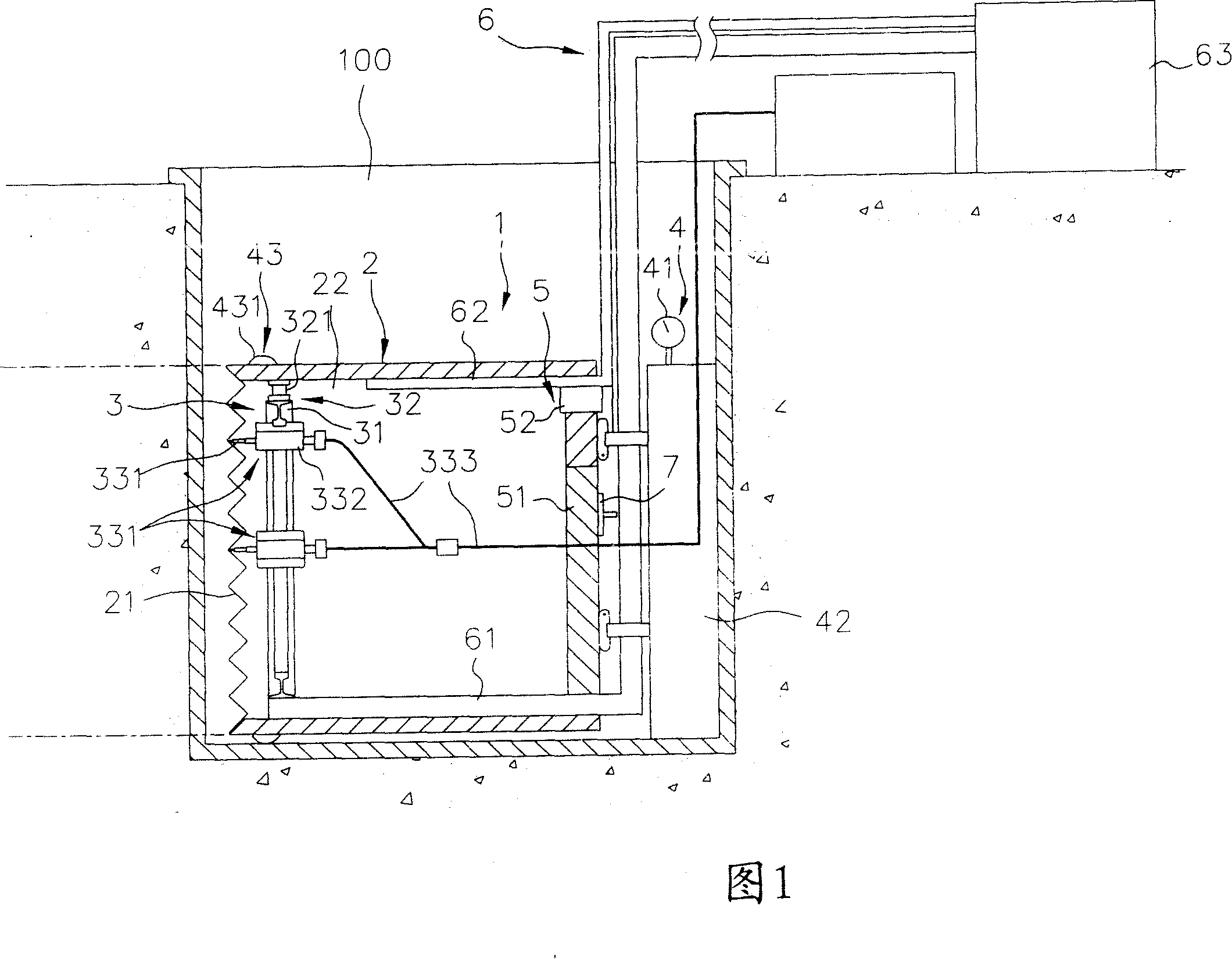
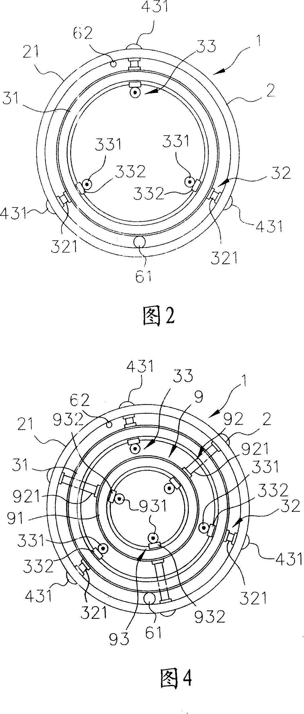
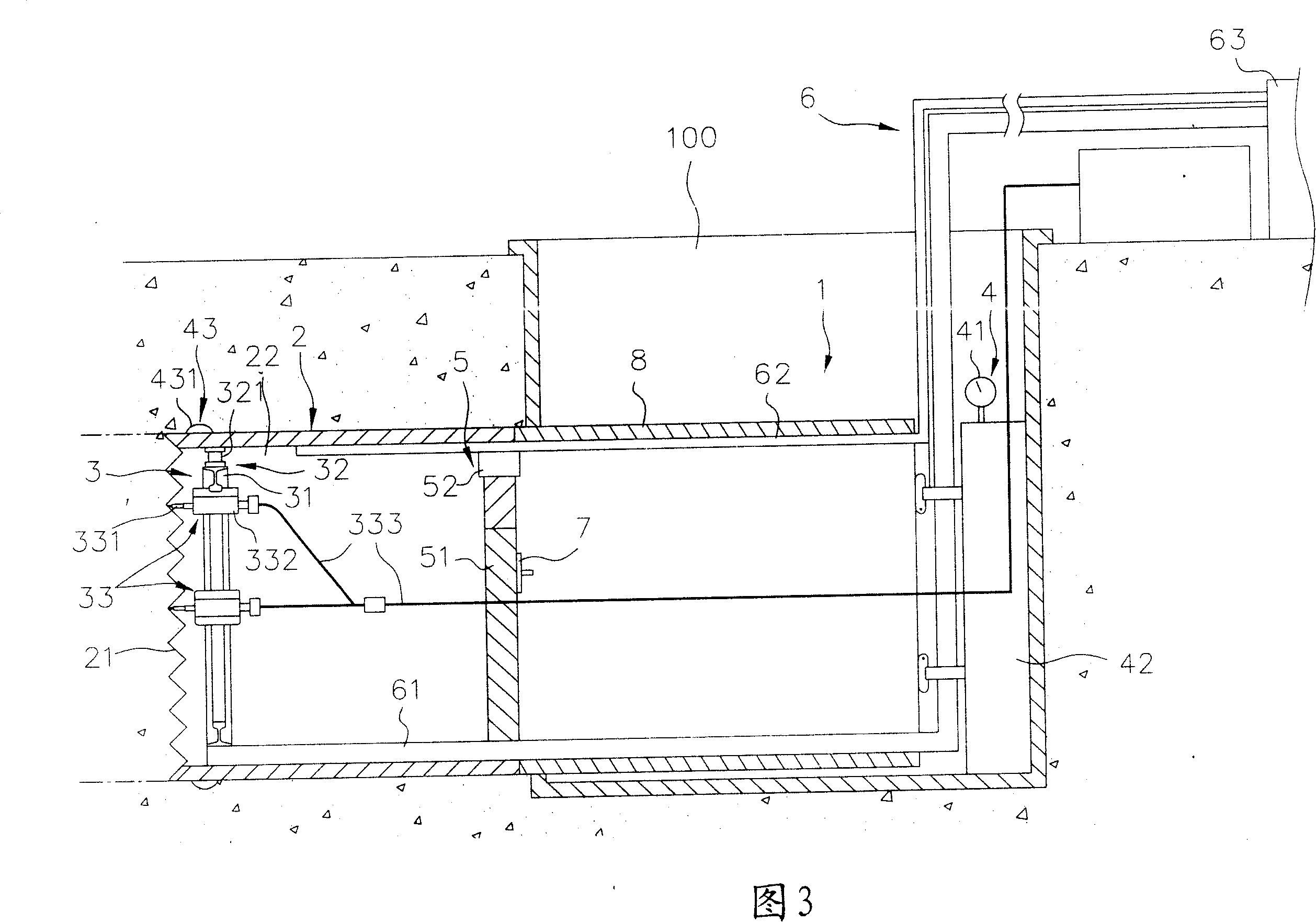
[0035] In order to further explain the technical means and effects of the present invention to achieve the intended purpose of the invention, the specific implementation of the non-contact demolition propulsion mechanism for cementing the ground proposed according to the present invention will be described below in conjunction with the accompanying drawings and preferred embodiments. , structure, feature and effect thereof, detailed description is as follows.

[0036] Please refer to Fig. 1, Fig. 2 and Fig. 3, a first preferred embodiment of a non-contact demolition propulsion mechanism for cemented ground in the present invention can be from the working well 100, along the working well 100 Excavate the corresponding cementing material structure forward in any normal direction of the wall, and then form a pipeline between the working well 100 and another working well 100 that is spaced apart, wherein the cementing ground is such as rock plate, egg without groundwater A gravel ...


PUM


Abstract

The non-contact cementing stratum breaking and pipe pushing mechanism includes one main pushing pipe, one non-contact cementing stratum breaking set mounted in the front end of the main pushing pipe, one hydraulic pushing set applying force to the main pushing pipe to go forward or alter direction, one pumping set to convey the broken cementing material to the well for removing, and one main pushing pipe sealing set to seal the back end of the main pushing pipe. The non-contact breaking set includes one hydraulic slide way inside the main pushing pipe, and at least one hydraulic knife to jet high speed fluid breaking the cementing stratum. The present invention can push forwards in cementing stratum to form ring pipeline without jamming, and is suitable for different geologic frameworks.

Description

technical field [0001] The invention relates to a machine tool used for breaking and excavating pipelines, in particular to a non-contact breaking propulsion mechanism for breaking cemented material sites. Background technique [0002] Constrained by the existing landscape, buildings and facilities in the metropolitan area, as well as avoiding too much impact on the busy traffic in the metropolitan area, as well as avoiding damage to the ecology and surface water and soil conservation, the use of the advancing construction method can effectively suppress this problem, so Underground construction has become an inevitable engineering construction technology for construction operations in urban areas; and when underground construction is in progress, the propulsion mechanism for breaking and digging formed pipelines from the working shaft wall is an indispensable and necessary machine tool. [0003] However, at present, most of the site characteristics in our country belong to ...

Claims


Application Information

Patent Timeline
IPC IPC(8): F16L1/028
Inventor 郑品聪
Owner TAIWAN WATERJET TECH
Learn More