Tank type container

A tank container and tank body technology, applied in the directions of packaging, transportation and packaging, containers, etc., can solve the problems of the tank container bottom beam bearing excessive load and reducing the distance, and achieve the effect of improving the stress condition and the use efficiency.

Active Publication Date: 2008-11-12
NANTONG TANK CONTAINER CO LTD
View PDF0 Cites 15 Cited by
  • Summary
  • Abstract
  • Description
  • Claims
  • Application Information

AI Technical Summary

Problems solved by technology

[0002] In the existing tank container, the end of the bottom beam of the end frame has a certain thickness of the reinforcing plate welded to the outer surface of the bottom beam rectangular tube wall. Due to this structure, the lower surface of the bottom corner piece of the end frame and the lower surface of the end of the bottom beam The distance between them is reduced, which often makes the end of the bottom beam contact with the bottom plate of the transport vehicle, causing the bottom beam of the tank container to bear excessive load

Method used


Image

  • Tank type container
  • Tank type container
  • Tank type container

Examples


Embodiment 1

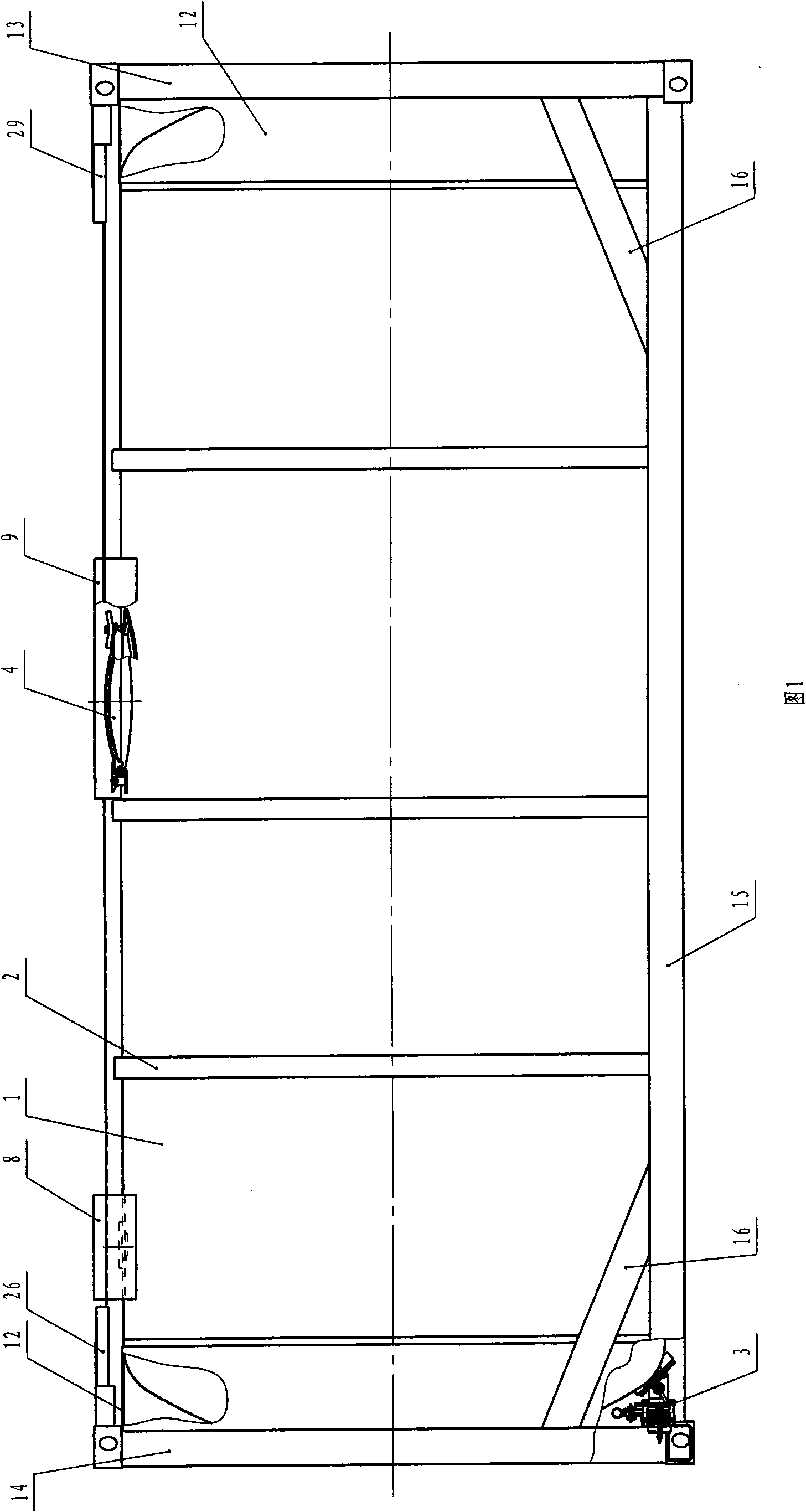
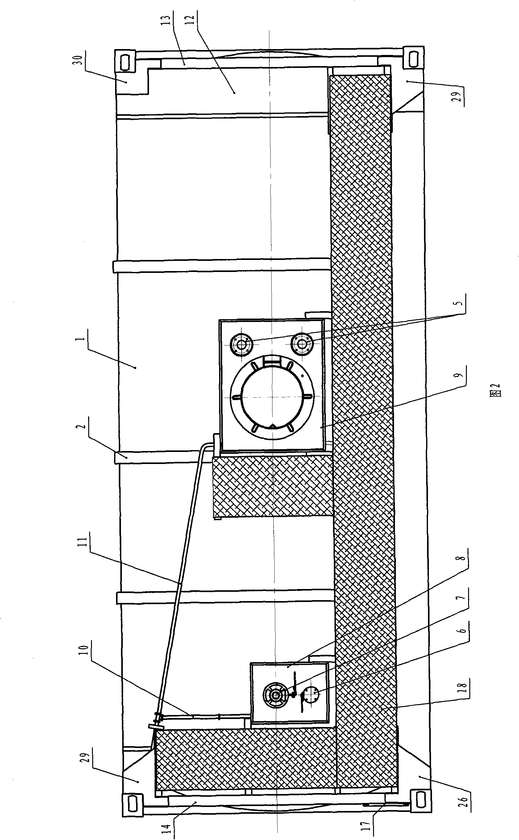
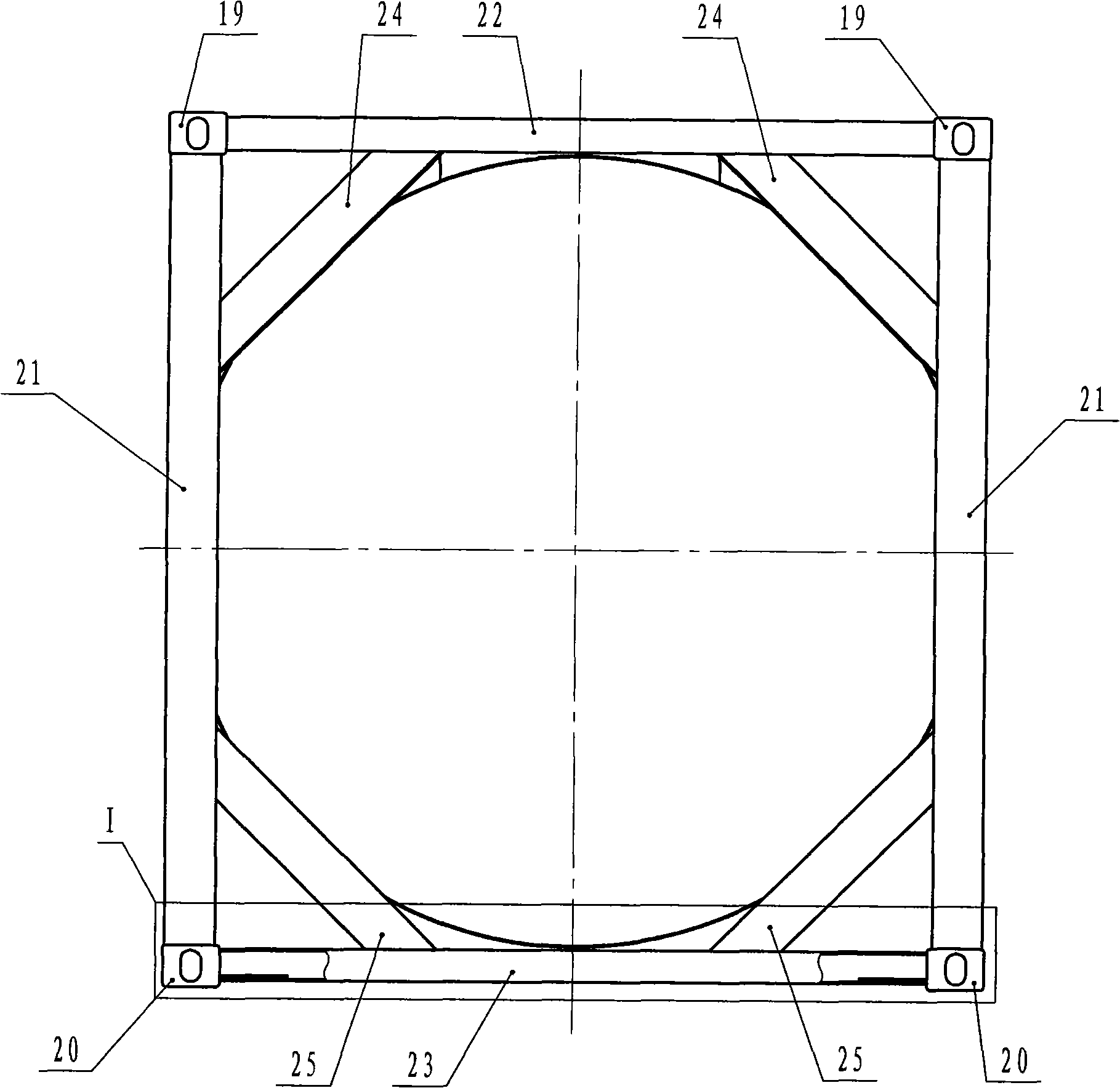
[0030] A tank container (see Figure 1 and Figure 2) has a tank body 1, a reinforcement ring 2 outside the tank body, a bottom discharge valve 3 placed under one end of the tank body, a manhole 4 on the top of the tank body, a safety valve 5, and a gas phase valve 6. Top outlet 7 and overflow boxes 8 and 9, overflow pipes 10 and 11 for leading the liquid in overflow boxes 8 and 9 to the outside of the tank container respectively at the bottom of overflow boxes 8 and 9. The two ends of the tank body 1 are welded with skirt rings 12, and the skirt rings 12 at both ends are respectively welded to the end frames 13 and 14 at both ends, and the end frames 13 and 14 are respectively connected with the longitudinal bottom beam 15 and the reinforced diagonal brace 16, An escalator 17 is fixedly installed on the end frame 14, and the escalator 17 leads to a walkway plate 18 fixedly installed on the top of the tank container. End frame 13 (see image 3 ) consists of top corner fittings 1...

Embodiment 2

[0032] The difference from Embodiment 1 is that the upper reinforcing braces 24 of the end frame 13 and the end frame 14 are made of angle steel materials, which can be processed by folding profiles or plates.

Embodiment 3

[0034] The difference from Embodiment 1 or 2 is: in order to reduce the processing steps of the walkway slab 18, reduce the number of walkway slab supports, and reduce the cost, the top corner plate 26 and the top corner plate 29 at the place where the walkway slab is installed are provided with a walkway Plate shelving edge 31 (see Fig. 7, Fig. 8, Fig. 9, Fig. 10); the top gusset without walkway board can adopt the same form as top gusset 26 and top gusset 29, also can adopt not to set The top gusset 30 (see Fig. 11 and Fig. 12) of the resting edge of the walkway slab.


PUM


Abstract

The invention relates to a tank-shaped container, comprising a tank body, a reinforcing ring arranged on the outer side of the tank body and a bottom discharging valve arranged below one end of the tank body. A manhole, a safety valve, an air-phase valve, a top discharging hole and an overflowing box are arranged on the top of the tank body. An overflowing tube used for guiding liquid in the overflowing box to the outside of the tank-shaped container is arranged at the bottom of the overflowing box. The two ends of the tank body are respectively welded onto the end frames of the two ends by apron rings, and the end frames of the two ends are respectively connected with a vertical bottom beam and a reinforcing inclined support. A stair fixedly arranged on the end frame of one end is led to a path board fixedly arranged on the top of the tank-shaped container. An angle part, an angle column, a top beam, a bottom beam, the reinforcing inclined support and a top angle board are connected to form the end frame. A reinforcing plate is welded on the internal surface of the lower wall of a rectangular tube of the bottom beam. The tank-shaped container has the main advantages that the distance between the lower surface of the end part of the bottom beam of the end frame and the lower surface of the angle part of the end frame is enlarged, therefore, the stressing condition of the bottom beam of the end frame during conveying is enhanced and the service efficiency of the tank-shaped container is improved.

Description

Technical field: [0001] The invention relates to a tank container. Background technique: [0002] In the existing tank container, the end of the bottom beam of the end frame has a certain thickness of the reinforcing plate welded to the outer surface of the bottom beam rectangular tube wall. Due to this structure, the lower surface of the bottom corner piece of the end frame and the lower surface of the end of the bottom beam The distance between the tank containers is reduced, and the end of the bottom beam is often in contact with the bottom plate of the transport vehicle, causing the bottom beam of the tank container to bear an excessive load. Invention content: [0003] The purpose of the present invention is to provide a technical solution for a tank container, which increases the distance between the lower surface of the bottom beam end of the end frame and the lower surface of the corner fittings of the end frame to ensure It is in full contact with the bottom plat...

Claims


Application Information

Patent Timeline
Patent Type & Authority Applications(China)
IPC IPC(8): B65D88/12B65D90/00B65D90/20B65D90/06
Inventor 戈登·哈里森楼晓华张俞忠
Owner NANTONG TANK CONTAINER CO LTD
Why Eureka
Try Eureka