

Water flow electric generating apparatus
A water flow power generation and water flow technology, which is applied in the direction of engine components, machines/engines, mechanical equipment, etc., can solve the problems of low conversion utilization rate and water energy conversion utilization rate, and achieve high-efficiency conversion, extensive and efficient conversion and utilization Effect
Inactive Publication Date: 2008-11-12
苗凤祥
View PDF0 Cites 3 Cited by
- Summary
- Abstract
- Description
- Claims
- Application Information
AI Technical Summary
Problems solved by technology
These power devices have low conversion and utilization rate of water energy, especially for the conversion and utilization rate of water energy without drop flow.
Method used
View moreImage
Smart ImageViewing Examples

Examples
specific Embodiment approach
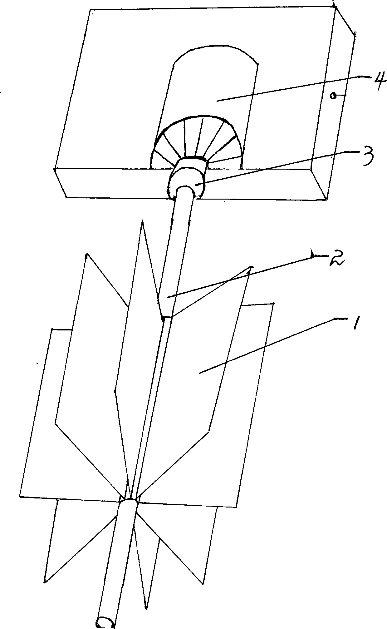
[0008] Specific embodiments of the present invention: as shown in the accompanying drawing, several rectangular or square rolling plates 1 of the same size that are compatible with the requirements of water flow and generator power generation are evenly distributed on the roller 2 along the direction of the roller 2, and the roller 2 and The generator rotor 3 installed in the middle part of the generator 4 is connected.
Login to View More PUM
 Abstract
The invention provides a water flow generating set which comprises an idler wheel and a generator, wherein, the idler wheel is composed of an idler wheel axel and a plurality of rectangular or foursquare rolling plates with same size which are evenly distributed on the idler wheel axel along the idler wheel axel direction and accord with the water flow and the power generation requirements of the generator; the idler wheel is connected with the rotor of the generator by the idler wheel axle; water flow pushes the idler wheel and the rotor of the generator to rotate by lashing the rolling plates on the idler wheel so as to realize the transformation of hydraulic energy of water flow to electrical energy. The hydro generating set of the invention can transform the hydraulic energy of water flow efficiently, and especially transform the hydraulic energy of water flow without head drop, thus realizing the high-efficient and broad transformation and utilization of the hydraulic energy of water flow, especially the hydraulic energy of water flow without head drop.
Description
field of invention [0001] The invention relates to a power generating device, in particular to a water flow power generating device. Background technique [0002] At present, the driving devices of the known water current generating devices are all made of turbines or paddle wheels. These power devices have relatively low conversion and utilization ratios of water energy, especially lower conversion and utilization ratios of water energy for non-fall water flow. Contents of the invention [0003] The object of the present invention is to provide a water flow power generation device. It can not only efficiently convert the water energy of the water flow with a drop, but also efficiently convert the water energy of the flow without a drop, and realize the efficient conversion and utilization of the water energy of the water flow, especially the water energy of the flow without a drop. [0004] The technical solution of the present invention: a water flow power generation d...
Claims
Login to View More Application Information
Patent Timeline
 IPC IPC(8): F03B13/00
Inventor苗凤祥
Owner苗凤祥