
Method for correcting circle center error of circular index point when translating camera perspective projection

A technology of perspective projection transformation and marker points, applied in image analysis, image data processing, instruments, etc., can solve the problem of increased calculation

Inactive Publication Date: 2008-11-12
HAIAN COUNTY SHENLING ELECTRICAL APPLIANCE MFG +1
View PDF0 Cites 29 Cited by
  • Summary
  • Abstract
  • Description
  • Claims
  • Application Information

AI Technical Summary

Problems solved by technology

In the document "A Four stepCamera Calibration Procedure with Implicit Image Correction". (Janne Heikkila, Olli Silven, IEEE Proceedings of Computer Society Conference on Computer Vision and Pattern Recognition, 1997: 1106~1112). It is pointed out that the circle will be The center of the ellipse in the image is not the real position of the projected point of the center of the circle in the image, that is, there is a deviation in the center of the two, so when using the circle as the mark point on the calibration board, it is necessary to This circle center deviation is corrected and compensated, and a method of correcting the circle center deviation is given in the literature. This method needs to first calibrate the camera to obtain the positional relationship between the calibration object and the camera, and then perform calibration again to realize the circle center deviation. compensation, the amount of calculation increases significantly

Method used


Image

  • Method for correcting circle center error of circular index point when translating camera perspective projection
  • Method for correcting circle center error of circular index point when translating camera perspective projection
  • Method for correcting circle center error of circular index point when translating camera perspective projection

Examples


Embodiment Construction

[0031] The following is a more detailed description of specific embodiments of the present invention with reference to the accompanying drawings:

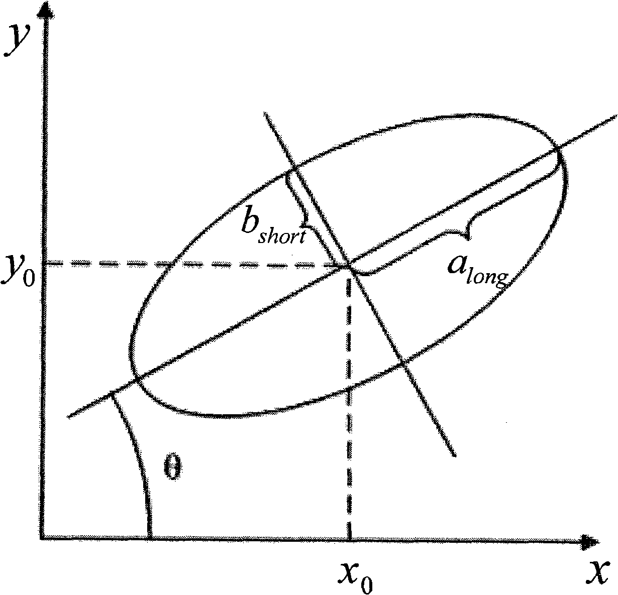
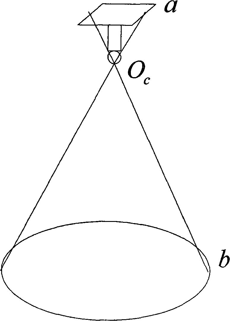
[0032] Due to the advantages of rotation invariance, easy identification, high positioning accuracy and insensitive to threshold value in image processing, circular marker points are widely used in various camera positioning occasions, but after perspective projection transformation, the space The middle circle becomes an ellipse in the image, and the center of the ellipse is not the position of the real projection point in the image after the perspective projection transformation of the center point of the circle in space, such as Figure 4 As shown, the cause of the center deviation in the perspective projection transformation is in the document "A Four step Camera Calibration Procedure with Implicit Image Correction". (Janne Heikkila, Olli Silven, IEEE Proceedings of Computer Society Conference on Computer Vision and Pattern Reco...


PUM


Abstract

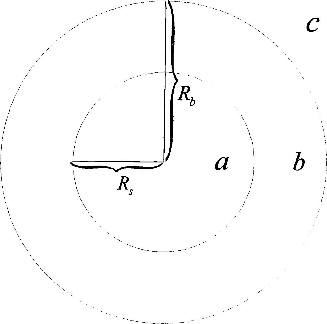
The invention relates to a correction method for circle center deviation of a circular mark point when a video camera carries out perspective projection transformation, which is characterized in that the method for setting the circular mark point comprises a step of arranging concentric circles consisting of a large circle and a small circle; the method for acquiring the data of the circular mark point in the image comprises steps of acquiring the image, applying filtration, threshold segmentation, edge detection, contour extraction and least square method ellipse fitting to the image to derive a link of the circle centers of ellipses in the image corresponding to the large circle and the small circle of the concentric circles; the link is intersected with the edges of the ellipses to which the large circle and the small circle of the concentric circles correspond in the image to generate four intersection points; the invariance of cross ratio in projective transformation is hired to derive the real positions of the projection points of the circle centers of the large circle and the small circle of the concentric circles in the image.

Description

technical field [0001] The invention relates to the field of computer vision detection, in particular to a method for correcting the deviation of the circle center of a circular mark point when the perspective projection transformation of a camera is performed. Background technique [0002] One of the basic tasks of computer vision is to calculate the three-dimensional information of the object in the field of view from the image captured by the camera, so as to reconstruct and recognize the three-dimensional object. The relationship between the three-dimensional geometric information of the object surface point and its corresponding point on the image is determined by the imaging model of the camera. The process of establishing this geometric model is actually the solution process of the camera parameters. Therefore, the calibration of camera parameters is the premise and key of this modeling process. The process of solving the camera parameters is called camera calibratio...

Claims


Application Information

Patent Timeline
IPC IPC(8): G06T7/00
Inventor 达飞鹏邢德奎
Owner HAIAN COUNTY SHENLING ELECTRICAL APPLIANCE MFG
Learn More