Parallel processing method for de-locking filtering in video encoding/decoding system

A video codec and parallel processing technology, applied in digital video signal modification, television, electrical components, etc., can solve the problems of low versatility and large number of filter cycles, and achieve improved processing efficiency, strong scalability, and filter cycle The effect of number reduction

Active Publication Date: 2008-11-12
ANYKA (GUANGZHOU) MICROELECTRONICS TECH CO LTD
View PDF0 Cites 43 Cited by
  • Summary
  • Abstract
  • Description
  • Claims
  • Application Information

AI Technical Summary

Problems solved by technology

But the number of filtering cycles is still too much, and requires a specific storage structure, and the versatility is not high

Method used


Image

  • Parallel processing method for de-locking filtering in video encoding/decoding system
  • Parallel processing method for de-locking filtering in video encoding/decoding system
  • Parallel processing method for de-locking filtering in video encoding/decoding system

Examples


Embodiment 1

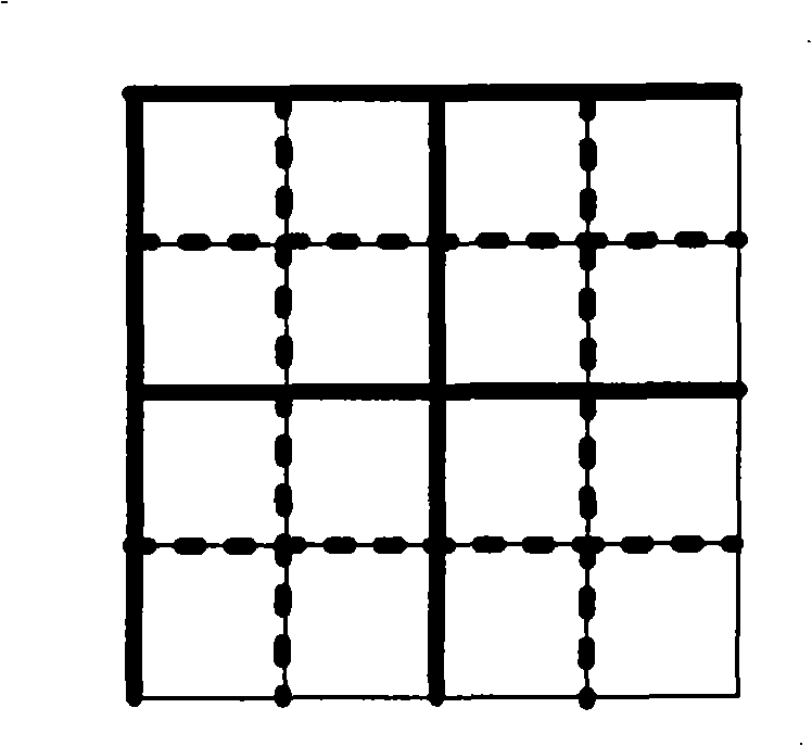
[0034] Embodiment 1: as Figure 7 In, the filtering of the sub-block boundary V9

[0035] Specific implementation steps:

[0036] Step 1. Read the sub-block sample points on both sides of the sub-block boundary V9 into the register array.

[0037] Step 2. Calculate the filtering strength of the V9 through the filtering parameters.

[0038] Step 3, if Figure 5 , simultaneously filter the 4 sample points on the boundary.

[0039] The following are further examples.

Embodiment 2

[0040] Embodiment 2: use such as in codec deblocking filtering operation Figure 7 The specific implementation steps of register arrays A and C shown in:

[0041] Step 1. Read in the data of the leftmost 4 sub-blocks I of the register array C.

[0042] Step 2. Simultaneously filter the sub-block boundaries V0, V1, V2, and V3 on a straight line, and read in the four sub-block data of II at the same time.

[0043] Step 3: Simultaneously filter the sub-block boundaries V4, V5, V6, V7 on a straight line, and simultaneously read in the data of the four sub-blocks of III.

[0044] Step 4: Simultaneously filter the sub-block boundaries V8, V9, V10, V11 in a straight line, and read in the four sub-block data of IV at the same time.

[0045]Step 5: Simultaneously filter the sub-block boundaries V12, V13, V14, V15 on a straight line, if there is data in A, write out the data in A at the same time.

[0046] Step 6. Read the data of the 4 sub-blocks above the macro block into A.

[00...

Embodiment 3

[0053] Embodiment 3: use such as in codec deblocking filtering operation Figure 7 Register arrays A, B, and I' shown in

[0054] Specific implementation steps:

[0055] Step 1, read in the first 4×4 sub-block of the first column of the filtered macroblock into I'.

[0056] Step 2. Filter the vertical boundary V0, and simultaneously read the second 4×4 sub-block in the first column of the filtered macroblock into I’ and the first 4×4 sub-block above the macroblock into B.

[0057] Step 3, filter the vertical boundary V4, read in the 3rd 4×4 sub-block of the 1st column of the filtered macroblock into I’ and the 2nd 4×4 sub-block above the macroblock into B.

[0058] Step 4. Simultaneously filter the vertical boundary V8 and the horizontal boundary H0, and simultaneously read the fourth 4×4 sub-block in the first column of the filtered macroblock into I′ and the second 4×4 sub-block above the macroblock into B .

[0059] Step 5. Simultaneously filter the vertical boundary V1...


PUM


Abstract

The invention discloses a parallel processing method for low-pass deblocking filters in a video encoding and decoding system. The inside of each macroblock corresponding to video data is divided into each subblock boundary for filtering wave. Each boundary of each subblock in the deblocking wave filtering has just once strength calculation of wave filtering. The threshold value calculation and the wave filtering process of each sample point on each boundary after the strength calculation of wave filtering are processed in parallel; the wave filtering of multiple subblock boundaries with specific arrangement rule in each macroblock is processed in parallel. After the method of the invention is used, the wave filtering periodicity is greatly reduced, and the processing efficiency of low-pass deblocking filters can be improved to a greater extent.

Description

technical field [0001] The invention relates to a filtering processing method, in particular to a parallel processing method for deblocking filtering in a video codec system. Background technique [0002] In a block-based video codec system, the image will appear blocky after the inverse transformation and quantization of the codec. There are two reasons for this. One of the most important reasons lies in the block-based DCT transformation of intra and inter prediction residuals. The quantization process of the transform coefficients is relatively rough, so the transform coefficients restored by the inverse quantization process have errors, which will cause visual discontinuity on the boundary of the image block. The second reason comes from motion compensated prediction. Motion compensated blocks may be copied from interpolated sample data at different locations in different frames. Since the matching of motion compensated blocks cannot be absolutely exact, data discont...

Claims


Application Information

Patent Timeline
Patent Type & Authority Applications(China)
IPC IPC(8): H04N7/26H04N7/50H04N19/117H04N19/436
Inventor 周林均张浩冯云庆庞恩林
Owner ANYKA (GUANGZHOU) MICROELECTRONICS TECH CO LTD
Why Eureka
Try Eureka