Coupling hook particularly for the lower arms of a three-point linkage of a tractor

A tractor and coupling ball technology, applied in the field of coupling hooks, can solve the problems of easy to use and sacrifice reliability

Active Publication Date: 2012-06-27
LH ELEVATOR
View PDF4 Cites 0 Cited by
  • Summary
  • Abstract
  • Description
  • Claims
  • Application Information

AI Technical Summary

Problems solved by technology

Ease of use cannot be built at the expense of reliability

Method used


Image

  • Coupling hook particularly for the lower arms of a three-point linkage of a tractor
  • Coupling hook particularly for the lower arms of a three-point linkage of a tractor
  • Coupling hook particularly for the lower arms of a three-point linkage of a tractor

Examples


Embodiment Construction

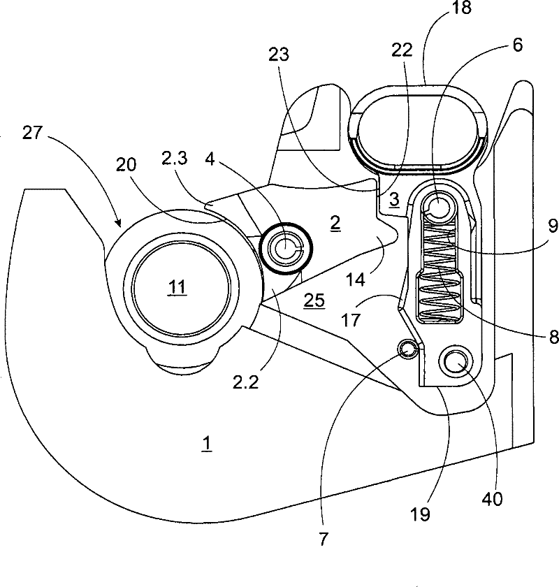
[0017] In the figure, the coupling hook according to the invention is shown without a cover, which is welded to the coupling hook in the final product. In addition, the coupling hook shown (Category 3, ISO 11001) is slightly smaller than the actual size.

[0018] The coupling hook itself is also attached to the lower arm by welding. The coupling hook includes a main body 1, which is provided with a coupling throat 27 and a housing 25, see Figure 1a . The operating mechanism of the pawl 2 is mainly located in the housing 25. The coupling throat 27 is conventional, which is especially arranged to receive the coupling ball 11. The coupling ball 11 is usually permanently installed in the appliance, or to a traditional three-point coupling pin. Similarly, even without a coupling ball, fast coupling can be performed, but this is not recommended. In addition, with the aid of the coupling ball, the small angular difference that may exist between the pin and the lower arm can be elimi...


PUM


Abstract

The invention relates to a coupling hook, more particularly a coupling hook for the lower arms of a three-point linkage of a tractor, which is intended to attach an implement to a tractor by means of a coupling ball 11. The body 1 includes a housing 25 for a catch mechanism and a coupling throat 27 arranged to receive particularly the coupling ball 11, and a catch 2 rotating in the housing 25 forlocking the coupling ball 11 into the coupling throat 27. In the free position, the catch 2 can rotate, thus permitting the coupling ball 11 to rise out of the coupling throat 27. The catch 2 is operated by an operating lever 3. The catch 2 is arranged to return the operating lever 3 to the locking position, when the coupling ball 11 rotates the catch, the catch rises out of the coupling throat.

Description

Technical field [0001] The present invention relates to a coupling hook especially used for the lower arm of a three-point lever mechanism of a tractor, which is used to attach an appliance to the tractor by means of a coupling ball or the like. The coupling hook includes: [0002] A main body, on which a housing for a detent mechanism and a coupling throat arranged to receive the coupling ball in particular; [0003] A detent that rotates around a fixed pin in the housing, the end of the detent protruding outwards from the housing into the coupling throat to lock the coupling ball in the coupling throat, and in a free position, it can rotate to allow coupling The ball rises from the coupling throat; [0004] The operating lever for operating the pawl is used to move the pawl from the holding position to the free position and back again. In the holding position, the operating rod prevents the pawl from rotating out of the coupling throat. Background technique [0005] The quick relea...

Claims


Application Information

Patent Timeline
Patent Type & Authority Patents(China)
IPC IPC(8): A01B59/00B60D1/04
CPCB60D1/04A01B59/006A01B59/043
Inventor P·维基T·维基P·昆普卡里奥S·普斯蒂宁
Owner LH ELEVATOR
Why Eureka
Try Eureka