Rail of electric vehicle

A vehicle and track technology, applied in the track field of electric vehicles, can solve problems such as uncontrollable speed

Inactive Publication Date: 2008-11-19
PRESTON & BARBIERI
View PDF0 Cites 0 Cited by
  • Summary
  • Abstract
  • Description
  • Claims
  • Application Information

AI Technical Summary

Problems solved by technology

[0009] Since the supply voltage is the electrical magnitude upon which the rotational speed of the DC motor depends, all vehicles of the bumper car ride are constrained to move on the track at substantially the same speed
Users have no control over the speed of their individual vehicles and can only activate or deactivate the electric motors by acting on the control pedal

Method used


Image

  • Rail of electric vehicle
  • Rail of electric vehicle

Examples


Embodiment Construction

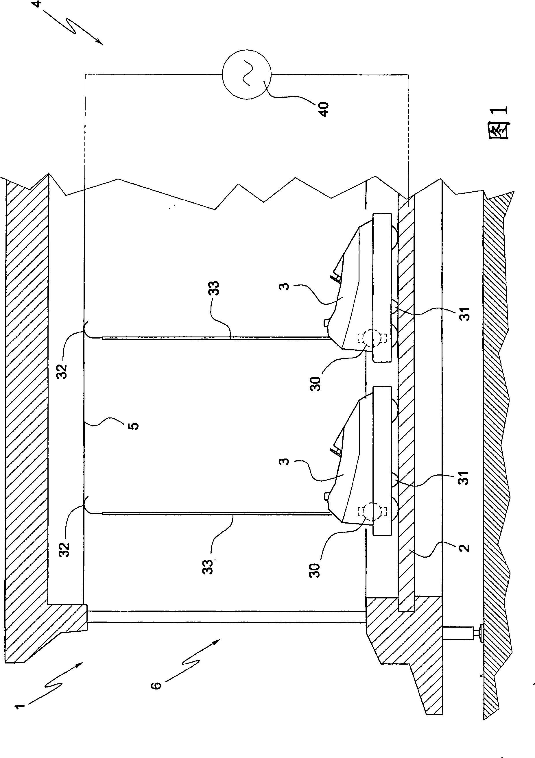
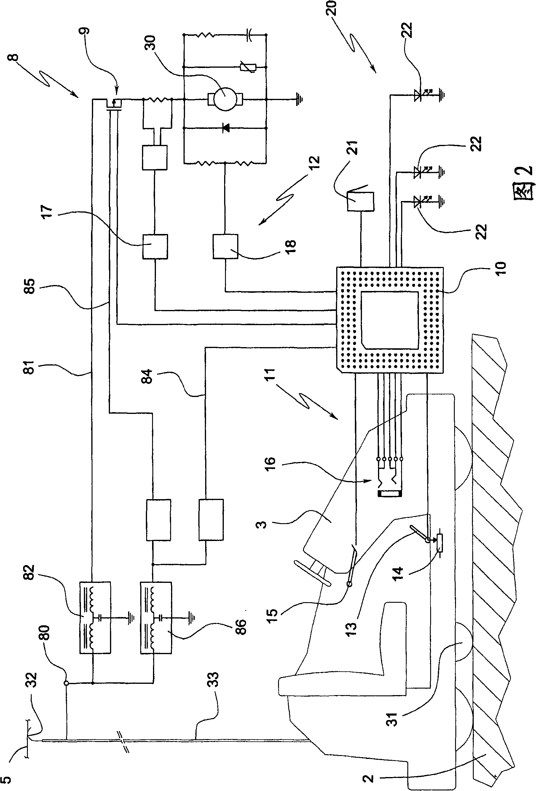
[0028] A bumper car ride 1 for fairs schematically shown in FIG. 1 includes a track 2 and a plurality of vehicles 3 that move freely on the track 2 in such a way that they can collide with each other to entertain their users.

[0029] An electric motor 30 , in this case a DC motor, is mounted on each vehicle 3 , which provides the torque necessary to propel the vehicle 3 concerned on the track 2 .

[0030] The electric motors 30 of all the vehicles 3 of the bumper car ride 1 are connected in parallel to a single power supply unit 4 associated with the track 2 .

[0031] As shown schematically in FIG. 1 , the power supply device 4 comprises a voltage generator 40 which generates a predetermined voltage difference between two electrical terminals located at a fixed position relative to the vehicle 3 .

[0032] In the example shown, the negative terminal is formed by a track 2 made of conductive material, while the positive terminal is formed by an overhead grid 5 also made of co...


PUM


Abstract

The invention discloses an orbit of electric vehicle. A vehicle riding device comprises an orbit (2) and a plurality of vehicles (3) which move on the orbit (2), supplied with power by a relevant motor (30) mounted on the vehicle (3) and are in parallel connection to a single power device (4) associated with the orbit (2). Each vehicle (3) comprises an adjusting device (9) for adjusting the rotating speed of the relevant motor (30) by the manner of basically independent to the motor (30) of other vehicles (3) of the vehicle riding device.

Description

technical field [0001] According to the preamble of claim 1, the invention relates to a track for an electric vehicle. [0002] More specifically, the present invention relates to a bumper car ride for use as an attraction in a fair. Background technique [0003] Bumper car rides are known to include tracks on which small electric vehicles move and collide with each other, the cars being provided with large rubber bumpers that absorb the impact. [0004] The vehicles are driven by individual electric motors, typically DC motors, mounted on the vehicles and connected to a single power supply unit associated with the track. [0005] Said power supply device generally comprises a voltage generator generating a predetermined voltage difference between two fixed electrical terminals to which all electric motors of the respective vehicles are connected. [0006] According to one broad embodiment, the first electrical connection is formed by a rail on which the vehicle moves. Th...

Claims


Application Information

Patent Timeline
Patent Type & Authority Applications(China)
IPC IPC(8): A63G25/00
Inventor M·费拉里
Owner PRESTON & BARBIERI
Why Eureka
Try Eureka