Highly effective radiation LED lamps

A technology of LED lamps and LED light sources, applied in lighting and heating equipment, parts of lighting devices, semiconductor devices of light-emitting elements, etc., can solve the problems of difficult heat dissipation of LED lamps, insufficient luminous brightness of single-chip LEDs, and poor effects.

Inactive Publication Date: 2008-11-19
史杰
View PDF6 Cites 14 Cited by
  • Summary
  • Abstract
  • Description
  • Claims
  • Application Information

AI Technical Summary

Problems solved by technology

Considering the insufficient luminance of a single LED, LED lamps generally adopt an LED array structure, which creates a rare problem of heat dissipation for LED lamps
[0003] In the Chinese Patent Application Publication No. CN1277665A document, a kind of LED lamp heat dissipation scheme is disclosed, in which the heat dissipation is to absorb the heat of the base connected to the LED through the connecting column in the lamp body, and then still dissipate heat in the lamp body, because it is Many times of indirect heat dissipation, and heat dissipation in the closed lamp body, the effect is not good
[0004] In the Chinese Patent Application Publication No. CN1359137A document, a heat pipe lamp heat dissipation scheme is disclosed. In this scheme, the heat dissipation of the scheme is to absorb the heat of the light emitting device through one end of the superconducting heat pipe, and transfer the heat to the heat sink of the lamp body in contact with the air at the other end. , because it is still multiple indirect heat dissipation, the effect is still not good
[0005] In the document of Chinese patent authorization announcement number CN2557805Y, a high-power LED lamp heat dissipation scheme is disclosed. In this scheme, the heat dissipation of the scheme is to absorb the heat of the LED through the air in the lamp body and transmit it to the lamp body heat sink in contact with the lamp body in contact with the air. It still belongs to indirect heat dissipation, and the effect is not good
[0006] In the document of Chinese patent application publication number CN1594962A, a kind of LED lamp heat dissipation scheme is disclosed. Heat dissipation, the effect is still not good
[0007] In the Chinese patent application publication number CN1605794A document, a heat dissipation scheme for LED spotlights is disclosed. In this scheme, the heat dissipation of the scheme is to absorb the heat of the LED through the air in the lamp body or the filling material and transmit it to the heat dissipation shell in contact with the air, which is still indirect heat dissipation. , still doesn't work well
[0008] In the Chinese Patent Application Publication No. CN1603679A document, a LED lamp heat dissipation scheme is disclosed, in which the heat dissipation of the scheme is that the heat of the LED (mainly the heat at the base of the LED) is transmitted to the heat dissipation plate through the circuit board and the conductive heat dissipation adhesive layer. , still indirect heat dissipation, still ineffective

Method used


Image

  • Highly effective radiation LED lamps
  • Highly effective radiation LED lamps
  • Highly effective radiation LED lamps

Examples


Embodiment 1

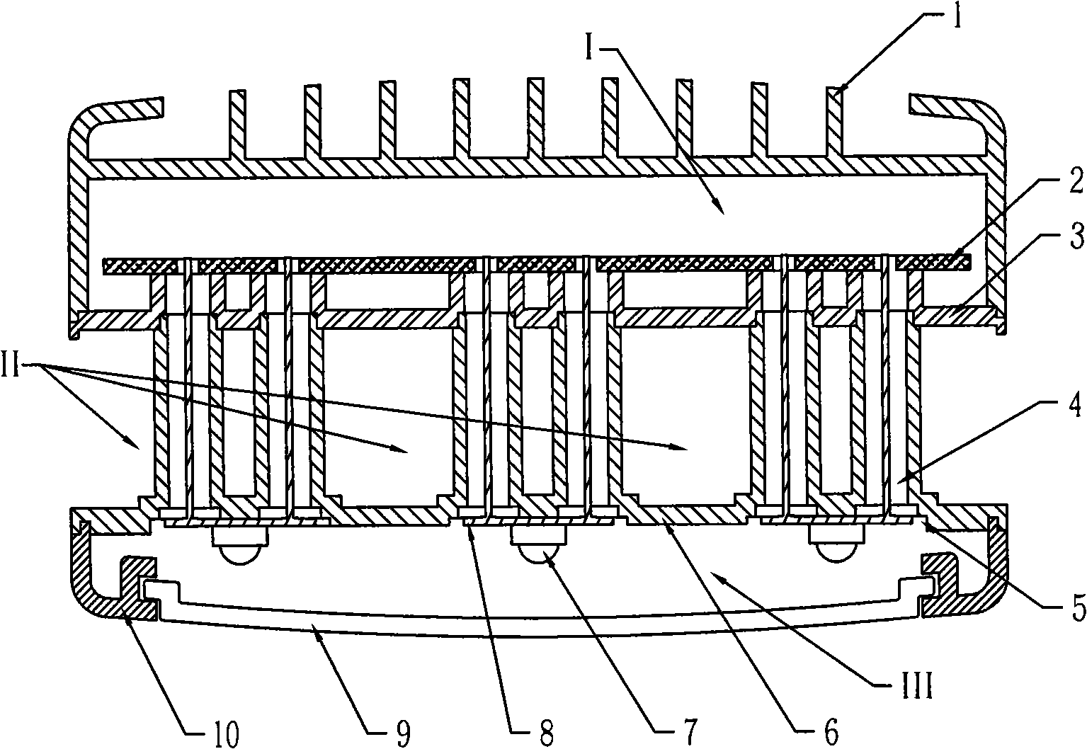
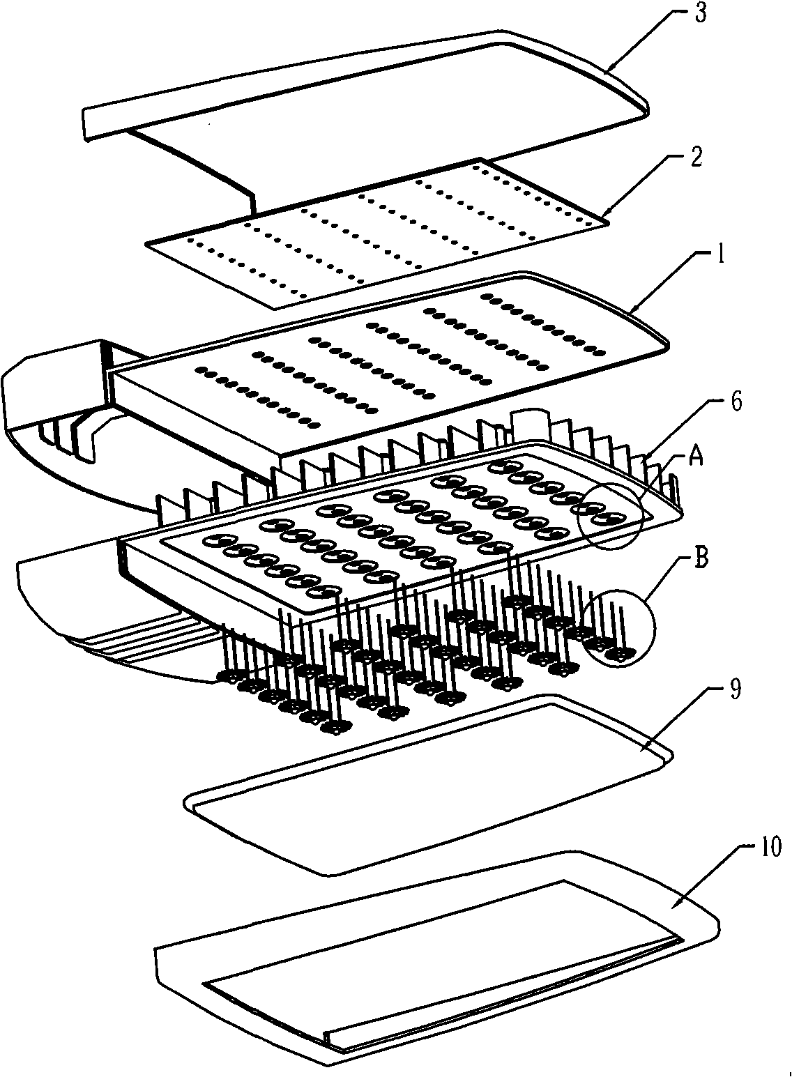
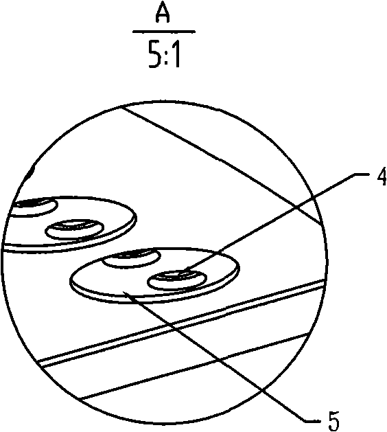
[0036] Example 1, such as figure 2 , as shown in Figure 3. The lamp head of the LED street lamp is long, and the lower surface of the open heat sink 6 is arranged with multiple LED light sources and lenses 7 along the vertical and horizontal directions; each LED light source and lens 7 are attached to the lower surface of the open heat sink 6 through the LED substrate 8. In the accommodation hole 5, the LED light source and lens 7 wires pass through the LED wire hole 4 to realize circuit connection with the PCB circuit board and corresponding electronic components 2, and most of the heat generated by the LED light source 7 is directly conducted to the open heat sink 6. From the surface to the upper part of the open heat sink 6, there are many grid-like heat conduction ribs arranged in a row. Since the open heat dissipation cavity part (II) of the lamp is directly exposed to the outside air, the natural wind from the outside passes through the upper part of the open heat sink ...

Embodiment 2

[0037] Example 2, such as Figure 4shown. LED tunnel light, the lower surface of the open heat sink 6 is arranged with a plurality of LED light sources and lenses 7 along the vertical and horizontal directions; each LED light source and lens 7 is attached to the LED accommodating hole 5 on the lower surface of the open heat sink 6 through the LED substrate 8 Inside, the wires of the LED light source and the lens 7 pass through the LED wire perforation 4 to realize circuit connection with the PCB circuit board and corresponding electronic components 2, and most of the heat generated by the LED light source 7 is directly conducted to the lower surface of the open radiator 6 until the open radiator 6 is opened. There are many grid-like heat conduction ribs on the upper part of the heat sink 6. Since the open heat dissipation cavity part (II) of the lamp is directly exposed to the outside air, the natural wind from the outside passes through the upper part of the open heat sink 6....

Embodiment 3

[0038] Embodiment 3, as shown in Figure 5. For LED spotlights, a plurality of LED light sources and lenses 7 are respectively arranged on the lower surface of the open heat sink 6 along the vertical and horizontal directions; each LED light source and lens 7 are attached to the LED accommodating hole 5 on the lower surface of the open heat sink 6 through the LED substrate 8 Inside, the wires of the LED light source and the lens 7 pass through the LED wire perforation 4 to realize circuit connection with the PCB circuit board and corresponding electronic components 2, and most of the heat generated by the LED light source 7 is directly conducted to the lower surface of the open radiator 6 until the open radiator 6 is opened. There are many grid-like heat conduction ribs on the upper part of the heat sink 6. Since the open heat dissipation cavity part (II) of the lamp is directly exposed to the outside air, the natural wind from the outside passes through the upper part of the op...


PUM


Abstract

The invention relates to a high heat dissipation LED lamp, which belongs to the lamp technical field. The LED lamp comprises a lamp body, and a PCB mounting plate, a PCB circuit board, an LED light source and a lens which are arranged on the lamp body. The LED lamp is characterized in that: the lamp body is provided with an LED electrical apparatus cavity, an open heat dissipation cavity and an LED lighting cavity which are sequentially connected into a whole; the LED electrical apparatus cavity consists of an upper cover plate, the PCB circuit board and the PCB installing plate; the open heat dissipation cavity is a space formed by installing a plurality of grille-like thermal conductive ribs in disorder on the upper part of an open heating body; and an LED wire hole and an LED receiving hole are arranged on the lower surface of the open heating body; the LED lighting cavity consists of the open heating body, the LED light source, the lens, an LED substrate, a lampshade and a lower cover plate. The LED lamp has the advantages of prolonging service life of LED lamps and keeping constant luminous effect, along with rational and compact structure, easy manufacture and good heat dissipation effect.

Description

technical field [0001] The invention discloses a high-efficiency heat dissipation LED lamp three-cavity structure design method and a lamp adopting the high-efficiency heat dissipation LED lamp three-cavity structure design method, in particular an array type high-power LED lamp. Background technique [0002] LED has the advantages of low energy consumption, low heat generation and long service life, and can completely replace traditional light sources. Considering the insufficient luminance of a single LED, LED lamps generally adopt an LED array structure, which creates a rare problem of heat dissipation for LED lamps. [0003] In the Chinese Patent Application Publication No. CN1277665A document, a kind of LED lamp heat dissipation scheme is disclosed, in which the heat dissipation is to absorb the heat of the base connected to the LED through the connecting column in the lamp body, and then still dissipate heat in the lamp body, because it is Multiple times of indirect h...

Claims


Application Information

Patent Timeline
Patent Type & Authority Applications(China)
IPC IPC(8): F21V29/00F21V17/10F21V19/00H01L23/367F21Y101/02
CPCF21S8/02F21W2131/406H01L2924/0002F21S8/04F21Y2101/02F21V29/20F21V29/225F21S8/06F21K9/137F21V29/004F21K9/233F21V29/70F21V29/763F21Y2115/10H01L2924/00
Inventor 史杰
Owner 史杰
Why Eureka
Try Eureka