High efficiency generator

一种发电机、AC电机的技术,应用在车辆的发电机系统,有源整流器电桥领域

Inactive Publication Date: 2008-11-19
GM GLOBAL TECH OPERATIONS LLC
View PDF0 Cites 17 Cited by
  • Summary
  • Abstract
  • Description
  • Claims
  • Application Information

AI Technical Summary

Problems solved by technology

In particular, the amount of power used to conduct the diodes gives a power loss of about 180 watts at 100 amps and a total diode voltage loss of about 1.8 volts

Method used


Image

  • High efficiency generator
  • High efficiency generator
  • High efficiency generator

Examples


Embodiment Construction

[0011] The following discussion relating to embodiments of the invention employing generator systems comprising active rectifier bridges comprising MOSFET switches is merely exemplary in nature and is not intended to limit the invention or its application or use.

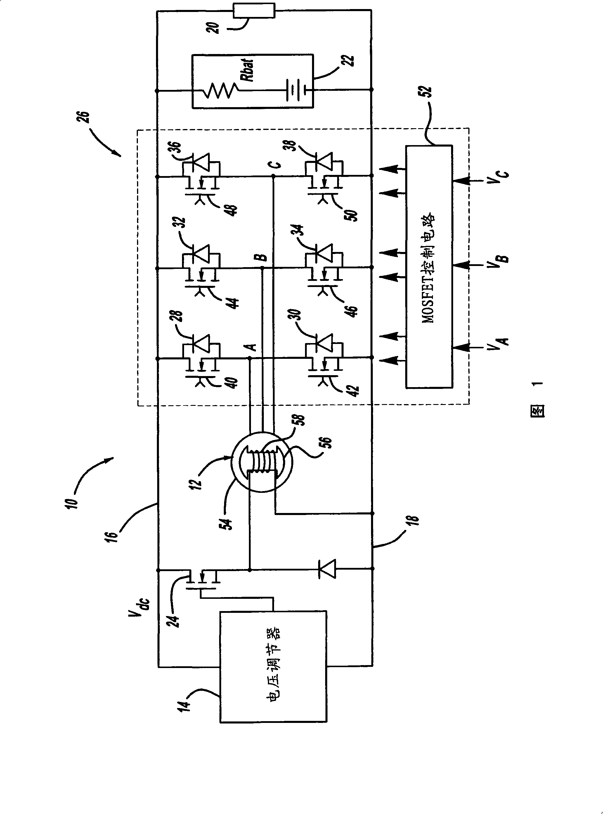
[0012] FIG. 1 is a schematic diagram of a generator system 10 according to an embodiment of the invention. System 10 includes a three-phase wound rotor synchronous electric machine 12 , such as a claw pole electric machine, having field coils 58 on a rotor 56 of electric machine 12 and three-phase AC synchronous armature coils on stator 54 of electric machine 12 . In a non-limiting embodiment, motor 12 is a Lundell motor. Permanent magnets are incorporated in the rotor 56 of the electric machine 12 between the claw poles to provide additional flux to the flux generated by the field coils 58, wherein the total flux is responsible for generating the voltage in the armature coils.

[0013] The system 10 also includes ...


PUM


Abstract

A generator system that includes a three-phase AC machine and an active rectifier bridge employing low on-resistance MOSFET switches for converting the AC current from the machine to a DC current. The system also includes a switch control circuit to switch the MOSFET switches in synchronization with the three-phase current flow. The system determines the phase-to-ground voltages of the machine as inputs to the switch control circuit. The control circuit calculates the phase-to-phase voltages from the phase-to-ground voltages. The control circuit then determines if each of the phase-to-phase voltages is above or below first and second predetermined threshold voltages, where if the phase-to-phase voltage is above the first threshold voltage, the control circuit closes the switch, and if the phase-to-phase voltage is below the second threshold voltage, the control circuit opens the switch.

Description

[0001] Cross References to Related Applications [0001] This application claims the benefit of US Provisional Application No. 60 / 938,537, filed May 17, 2007, entitled High Efficiency Generators. technical field [0002] The present application relates generally to a generator system, and more particularly to a generator system for a vehicle, which includes an active rectifier bridge employing low on-resistance metal-oxide-semiconductor field-effect transistor (MOSFET) switches, and controlling the switches control scheme. Background technique [0003] The vehicle employs a generator driven by a belt coupled to the vehicle's engine to generate electrical power. Automotive generators typically employ an AC synchronous motor with three-phase stator windings, a DC field winding on a claw-pole rotor, a voltage regulator, and a three-phase diode bridge rectifier to generate a DC output. The excitation current of the synchronous motor is controlled by a voltage regulator to adju...

Claims


Application Information

Patent Timeline
Patent Type & Authority Applications(China)
IPC IPC(8): H02J7/24H02P9/30H02M7/219
CPCH02M7/219H02P9/30
Inventor C·S·纳穆杜里L·郝
Owner GM GLOBAL TECH OPERATIONS LLC
Why Eureka
Try Eureka